
Power cables
MV cables in power networks
Transmission and distribution of large quantities of power, as in power networks, can be established in two ways: with overhead lines (or overhead cables) and with underground power cables. In the early days of electrification, cable technology was just in its beginnings so mainly overhead lines were used. Nowadays, power cables are available for a wide range of voltage and power levels.
Still, from an investment-costs point of view, overhead lines usually are preferred. However, regarding aesthetical and environmental considerations, safety issues, regulations but also technical matters, power cables can have the advantage.
Furthermore, if the operation costs, including maintenance, are taken into account, power cables can also be competitive, which especially applies for medium-voltage (MV) networks.
The installed power-cable length is also increasing, because of the ever increasing demand for power. This is especially the case for distribution-class cables, operating in the range of 1 kV – 36 kV. In many countries, a large part of the medium and low voltage grid is constructed with power cables.
In the Netherlands e.g., this is virtually 100 %. The total length of the MV cables in the Netherlands alone is already approximately 100,000 km, which corresponds to an investment of about 5×10⁹ euros.
In Figure 1.1 an example of a part of a ring-structured MV grid is drawn. As is indicated with dashed lines, several connections to other ring structures and substations are also possible and one substation usually feeds several rings.
Medium-voltage networks, especially in highly populated areas, are often designed with some version of this ring structure, so power delivery can be routed via several paths, to increase reliability and provide maintenance possibilities. Due to limited maximum lengths of MV cables, or partial replacements, joints are used to interconnect cable sections.
Considering the total costs of the complete power grid, the distribution grid takes the major part, in the Netherlands approximately 75 %. Optimal design and maintenance of the distribution grid is therefore crucial from an economical point of view.
A large part of the investment costs of the distribution network is taken by the medium voltage cables. Furthermore, the distribution grid is responsible for the majority of the time duration of power delivery failure to the customer. In the Netherlands this figure is about 80 %.
A vast majority of the distribution grid outage times is due to failures of MV cables and especially their joints. As many medium-voltage cable connections were already installed more than 30 years age, a preventive maintenance strategy, as was often applied in the past, would require replacement.
Provided that good knowledge of the condition of the system parts can be obtained, high cost reduction and reliability improvement can be established. As a consequence, good condition diagnostics for especially medium-voltage cables and their accessories (joints, splices, and terminations) have become very important.
Distribution-class power cable types
For medium voltage cables, two main categories can be defined: paper-insulated and extruded cables. Several variations of the specific materials and dimensions exist, but the general lay-out principles are briefly described by the two categories below.
Paper-insulated lead-covered cables
The paper-insulated lead-covered (PILO) cable is one of the oldest power-cable types and exists for almost a hundred years. For a long time, there have been no alternatives that could compete with the proven reliability of this type of cable and in many countries the majority of installed MV cables is still PILC.
Figure 1.2 shows an example of a commonly used PILC-type cable: a belted cable, which relates to the common belt (3) around the three phase cores (1+2). The phase conductors (1) can be stranded copper or aluminium or solid aluminium. The insulation consists of windings of paper tape, which is impregnated in a compound of oil, wax, and resin (2+3). The core-and belt-insulation thicknesses obviously depend on the operating voltage, which is for belted cables usually below 15 kV.
The lead shield (4), around the belt, serves as the earth conductor and ensures watertightness.
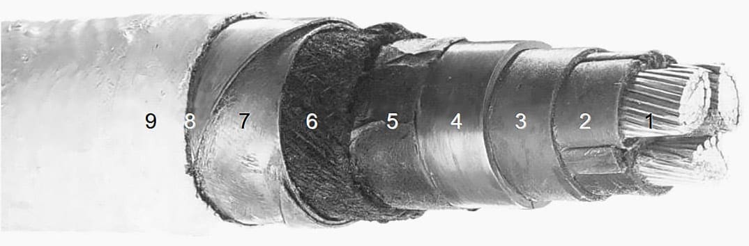
Further coverings are bitumenized paper (5), jute (6), steel armor tape or wires (7), bitumenized jute (8), and chalk (9). The bitumen is applied for preservation. The chalk is used to avoid sticking of the cable to the reel. A polymer sheath from PVC (polyvinyl chloride) or PE (polyethylene) sometimes replaces the jute and gives better protection against e.g. pitting or corrosion (due to e.g. stray currents).
Some characteristics of PILC cables are: rugged, compact, continuous earth screen, high chemical resistance due to the lead sheath and proven long service life. Especially due to this last characteristic, some utilities still favor this type of cable. This belted PILC cable is used extensively for distribution-class cables.
In the Netherlands, the vast majority of the medium voltage cables are belted PILC cables, mainly 10 kV. Therefore, the main focus of this thesis will be pointed at this cable type, although most principles are cable-type independent.
Other variations include e.g. the use of a separate lead sheath around each phase core and/or application of semi-conductor layers at the insulation-metal interfaces or as HochstUdter layers, to optimize field control.
The maximum voltage class for this type of cable is 69 kV, although 10-35 kV PILC cables are most commonly used.
Extruded solid-dielectric power cables
Although polymeric cables are already available since the early 1950s, it was only until several tens of years later that the reliability increased enough to compete with PILC cables. Even nowadays, PILC cables sometimes get the advantage, depending on the utility and application.
Although there are many different polymeric cable designs, an example of a single-phase XLPE (cross-linked polyethylene) cable is depicted in Figure 1.4 to present the general structure. Details may differ for various designs. For standardized names of the various layer, see [IECc].
Around the insulation, a semi-conducting shield (4) ensures smooth interfacing. This shield is also often denoted as insulation screen. Semi-conducting swelling tape (5) is applied for longitudinal watertightness. Copper or aluminium wires (6) and counter wounded tape (7) serve as the earth con-ductor and should accommodate capacitive and short-circuit currents.
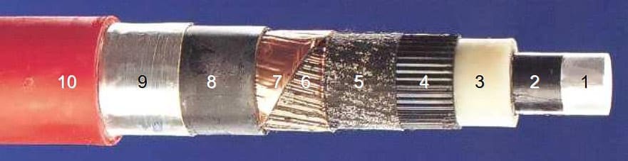
Around this screen, semi-conducting filling rubber (8) can ensure longitudinal watertightness at this location. An aluminium complex strip (9) and a PE or PVC sheath (10) serve as protection against water ingress and mechanical forces. Properties of extruded cables are:
- Low losses and relative permittivity,
- Long expected lifetime,
- Simple handling,
- Long lengths and,
- Especially if XLPE is used, high maximum operating temperature.
Extruded cables are not restricted to distribution class voltages. Maximum voltage rates are up to 500 kV. Just as the three-core PILC cables with one common (lead) shield, MV polymeric cables can also embed three cores in one cable.
Figure 1.5 shows an example. The several layers and materials in this structure are similar to those of the single-core design. Now each of the phase conductors and their insulation layers have their own semi-conducting screen around them, resulting in radial electric field distributions in the core insulation, as in the Hochstadter PILL cable.
| Title: | Online detection and location of partial discharges in MV cables – Petrus Carolina Johannes Maria van der Wielen, to obtain degree of doctor at Eindhoven University of Technology |
| Format: | |
| Size: | 5.5 MB |
| Pages: | 207 |
| Download: | Right here | Video Courses | Membership | Download Updates |

I have degre in Electrical and computer engineering (power stream) so i will want to study master please contact me if i will get this chance my mail [email protected] or +251919247307. Thanks