
Compensation of reactive power
The article analyses theoretical and practical solutions of reactive power compensation in the power grid of 25 kV, 50 Hz of the catenary. The article presents theoretical and practical studies (by providing circuits for connecting capacitor banks, structural circuits diagrams for the automatic control reactive power level, and calculating the parameters of capacitor banks) for the compensation of reactive power.

It is only lately that modern solutions have been applied in the area of reactive power compensation to not only reduce the costs for the use of reactive power but also to improve the quality of the energy system.
By compensating the reactive power in the power grid and filtering the harmonics of undesirable currents, higher quality of electric power in terms of voltage is ensured, and the losses of voltage and power are reduced.
The examples of how reactive power compensation can improve the technical-and-economic indexes of an industrial power grid are as follows:
- Reduce cost and generate higher revenue for the customer,
- Reduce network losses,
- Avoid penalty charges from utilities for excessive consumption of reactive power,
- Increase system capacity and save costs on new installations,
- Improve system power factor,
- Increase power availability, and
- Improve voltage regulation in the network.
Nowadays, static VAR compensators (SVCs) and static synchronous compensators (STATCOMs) are the most useful devices to control the dynamic reactive power level in the industrial grid.
This article presents some methods, showing the potential use of dynamic reactive power compensation via the series compensation devices SCB (capacitors banks) located in 25 kV AC catenary the arms of A, B phases and in the line of return current (see Figure 2).

Having analysed the supply system of alternating current 25 kV AC catenary, the author proposes to locate the series compensation devices SCB (capacitors banks) in the arms of A, B phases and in the line of return current and methods for dynamic reactive power value automatic control.
Compensation of reactive power by using capacitors
Capacitive compensation
Depending on the method of connecting capacitors with regard to loading (in parallel or in series), shunt or series capacitive compensation is singled out. A typical reactive power compensation scheme is used for industrial power system (Fig. 3a).
The author of the proposed reactive power compensation scheme for 25 kV, 50 Hz traction system (Figure at the top) examples of connecting reactive power capacitor banks, phasor diagrams where cosφ1 = 0.85 (before compensation) and cosφ2 = 0.97 (after are provided in Fig. 3c.
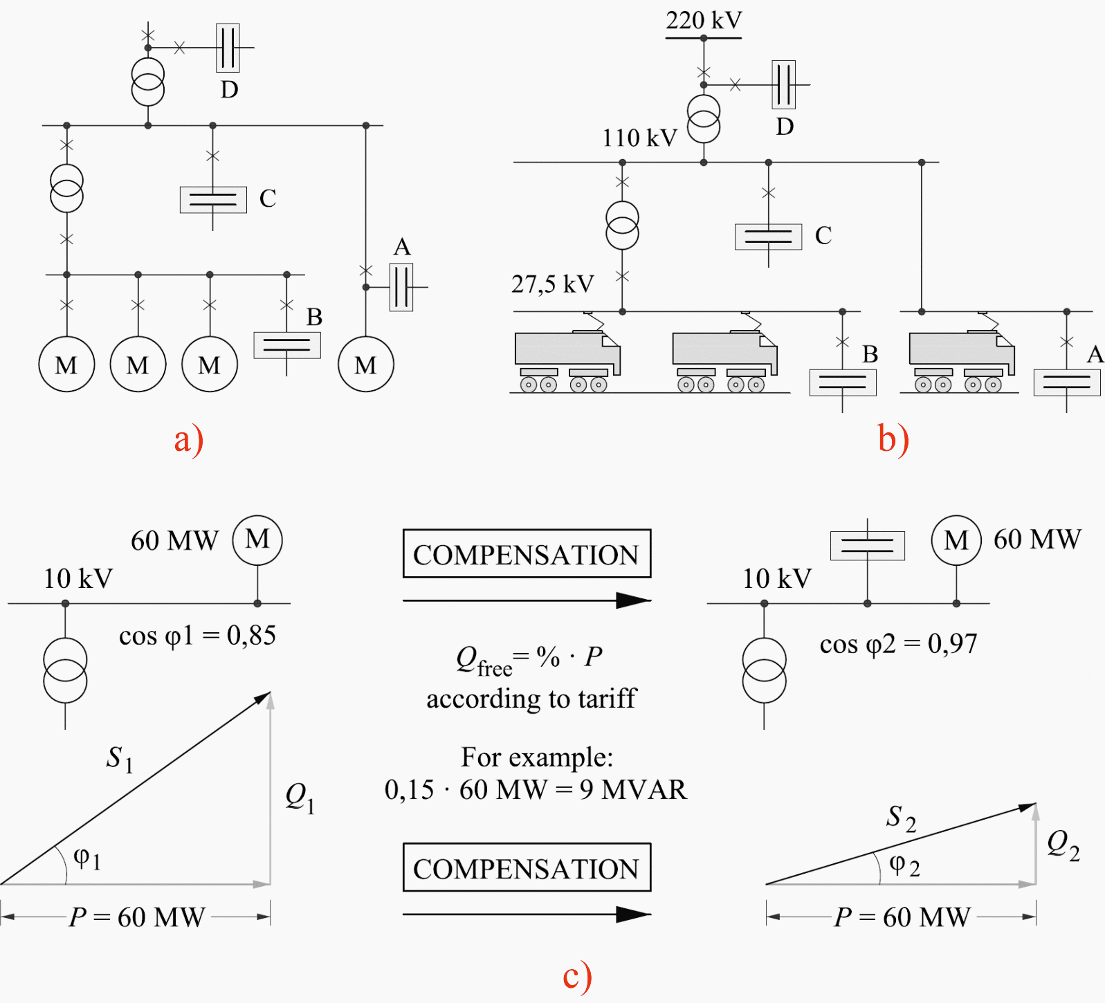
Possible locations of the capacitor bank offered by company ABB have been provided in Fig. 3a). The location is primarily determined by the reason for compensation:
- A: Direct Compensation
- B: Group Compensation
- C: Central Compensation at low voltage (LV) side
- D: Central Compensation at high voltage (HV) side.
The power triangle of an installation running at low cost and where the load of the transformer is close to full. The power triangle of the same installation where power factor correction has been applied reduces load on the transformer / releases capacity for additional loads.
| Title: | Reactive power compensation in the 25kV, 50Hz contact network by Lionginas LIUDVINAVIČIUS at Vilnius Gediminas Technical University, Department of Railway Transport; J. Basanavičius str. 28, LT-03224 Vilnius, Lithuania |
| Format: | |
| Size: | 0.9 MB |
| Pages: | 10 |
| Download: | Right here | Video Courses | Membership | Download Updates |


That’s good to control or minimize the reactive power losses in a network by capacitors compensation method. But please tell me something about “how to minimize the power losses of a network using the distributed generators” thanks and best regards junaid