Thesis Foundation
One of the main goals of this research is to make the solution implementable and practical in the real world. Due to this constraint the research could not recommend drastic solutions that would require a complete top down change in the way power is being delivered making the implementation too costly.

So while trying to use the existing structure the research is aimed at suggesting ways in which we could manage power efficiently while maintaining a relative low cost of upgrading old equipment to provide additional functionality in the existing electrical grid structure.
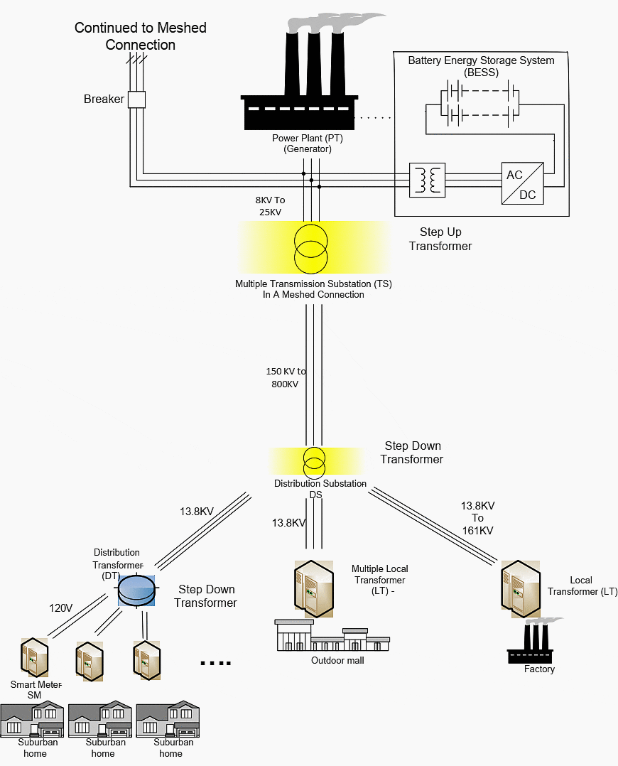
So let’s first look at a Source to Destination model of how and where power is generated to how it ends up in our home and businesses.
Source to Destination Model
PP (Power Plant)
Power gets generated at a power plant which come in different types and sizes. There are power plants that use fuel to generate electricity:
- Coal Fired Power Plants (coal)
- Combined/Simple Cycle Power Plants (Natural Gas)
- Nuclear Power Plants (Uranium a highly radioactive material).
Other than fuels there are other natural resources that are employed such as:
- Hydroelectric Power Plants which rely on immense pressure generated by a large water reservoir constrained with the use of a Dam.
- Wind Farms which harness wind energy.
- Solar Power Plants that utilize photovoltaic cells in large number to harness the energy imparted by the photons created by our Sun to generate electricity.
- Geo Thermal Plants generate power from the thermal energy that is generated by the core of the earth.
- Tidal Wave Power Plant harnesses the tidal motions of the sea to generate power.
TS (Transmission Substation)
TS (Transmission Substation) generally transmit power between 150KV to 800KV. Transmission Substations deliver power to the Distribution
substations.
Recommended reading:
Design of 33kV switchyard (equipment, SLD, and layout) for small hydro-power plant
DS (Distribution Substations)
DS (Distribution Substations) are generally located in areas of power consumption. The purpose of this Distribution Substation is to step down the voltage of the power that it receives from the Transmission Substation so that it can be sent out for local industrial and commercial consumption.
DT (Distribution Transformer)
The local transformer (single phase distribution transformer in case of residential area is generally responsible for providing power to 4 to 6 houses) then receives this power and steps down the power to 120V/240V which is then used by the consumer in their home.
SM (Smart Meter)
When we speak in the Smart Grid context but in general term we can refer to this as Meter. The meter is responsible for tracking electricity usage within a home/commercial organization or at the consumer.
The average consumption of the US house hold is 903 kWh (Kilo Watt Hour) per month during the 2012 year as reported by the US Energy Information Administration.

Overview of the Electrical Grid
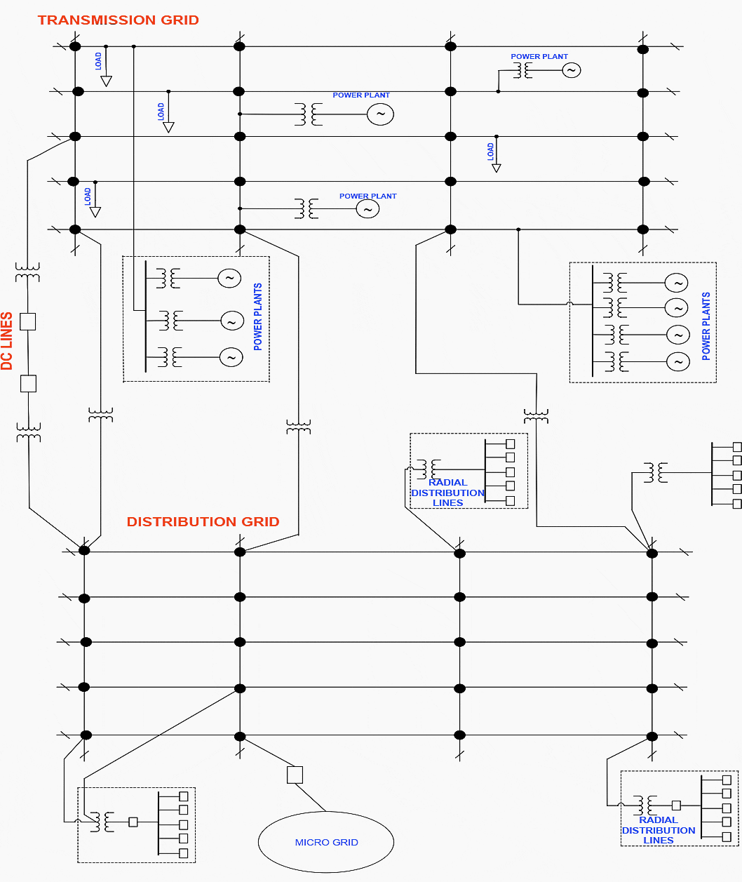
To form the basis of the research let’s look at the current grid system. The high voltage meshed grid consists of longer connections which have the highest voltage since this is where the power will travel the longest and then feed into smaller radial grids shown in Figure 1 as the commercial grid.
This in turn feeds into even smaller radial grids labeled as a residential grid.
Although the Figure 1 is ideal and symmetrical in the real world the actual structure of the grid might be more mixed and unusual while keeping the basic design structure and concepts the same.
Drawing Legend for Figure 1:

The transmission components of the grid are responsible for collecting power from the source and distributing this power to the distribution component, which then are charged with distributing it to the different type of consumers. The type of consumer is defined based on the size and the power utilized by the consumers.
The type of consumer will play an important role in determining how the proposed algorithm will manage and maintain satisfactory level of power supply to a particular grid based on what type it is.
We look at some of the factors that give the grid its signature structure.
Top Down Power Flow
As evident from Figure 1 and Figure 3 power is delivered is always delivered from top to bottom. Power plants are the sole producers of power and it flows to the consumers commercial/residential for consumption.
Redundancy
Another factor to consider in the figure 1 is redundancy due to the mesh structure of the grid. Any end consumer connected to this mesh grid takes advantage of the built in redundancy in the meshed structure to be able to consume power even if a predesigned number of transmission / distribution lines are out of service.
Non critical systems are usually designed to be serviced through a single substation and hence there is limited redundancy.
The description above is of an ideal system, so in reality there could be scenarios where residential part of the grid has extra redundancy built into it because it is connected to the source through multiple substations. All these are exceptions to the rule but in general practice follow the same source to load delivery of power.

Redundancy Based on Critical Function at End Consumer
All commercial institutions such as hospitals, prisons, police stations and fire stations are critical and require power to be functional and might choose to tap (connect) into the HV meshed grid at multiple points to remain functional in the worst of crisis.
On the other hand residential locations are non-critical and can afford to function as a primary shelter for its residents for a limited time.
1.4 Changes Needed for Smart Grid
Considering that we have to enhance the present grid system to function as a smart grid we have to make some very fundamental shifts in the way we think about generating and delivering power. There are some aspects of the current Grid Structure that we would want to keep such as redundancies due to meshed structure, and redundancy based on multiple connections to the meshed grid for critical consumers.
On the other hand we need to make the Smart Grid be able to handle power flow top to bottom as well as bottom-up. Let’s look at some of these upgraded requirements that we will need.
Easily Pluggable Power Source & Top Down and Bottom-Up Power Flow
One of the basic shift in thinking involved in a smart grid from the power generation and distribution perspective are that any node in the grid can have a power generating and consuming aspect to it, contrasting this to the legacy grid system in which, the main node is the only node that generates power, whereas the commercial and the residential nodes consumed power.
Example scenarios of a smart grid where nodes can be producers and consumers are:
Example #1
Solar panels on residential locations, qualify them as a producer of electricity, which if not completely consumed by the resident can be fed back into the grid.
Recommended reading:
Integration of renewable energy in smart grid (architecture, communication, and electric vehicles)
Example #2
Large commercial farms which have the acreage and environmental circumstances to support wind farms serve a dual purpose as a power producer
and a consumer.
Since the nodes can generate power and often times produce excessive power that is beyond the present requirement of that node they are capable of providing the excess power to any of the nodes they are connected to.
We look at a couple of examples where a node would generate enough power to have excess capacity which it can then share with adjacent nodes, leading us to make a fundamental change and requiring our grid system to be capable of providing power top down as well as bottom-up.
Example #3 – The Case
Assuming we have a residential location or residential node where large percentages of residences are solar panel equipped. The hours in a day when a residence consume the least power is also the time they may also generate the most amount of power.
This is because in many households residents are either away at work or at school during the day time, which is also the peak production time for solar systems. Now if this is a common trend where the power produced by each house hold is more than the power consumed.
This scenario also leads to a high amount of cost savings by utility companies which are responsible for providing electricity to residential and commercial locations.
In the above case where the residential nodes are producing excess power the utility company can purchase the power for a lower cost and supply to its commercial customers, hence reducing its overall cost (by avoiding remote power source and saving on transmission) and passing on the savings to its customers.
| Title: | A practical solution for self-adaptable smart electrical grid (implementable in the real world) – KUSHAL KUMAR LAL; A thesis presented to the Faculty the University of Missouri-Kansas City in partial fulfillment of the requirements for the degree MASTER SCIENCE |
| Format: | |
| Size: | 1.2 MB |
| Pages: | 68 |
| Download: | Right here | Video Courses | Membership | Download Updates |


