
Earth Switches
Fixed earth switches are fully rated for the system earth fault current. Operationally they must be used as preferred program earths wherever they are installed. Testing for de-energisation of the line must be carried out, using an approved test instrument before the earth switch is closed.
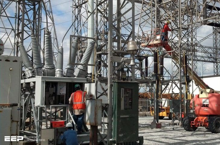
Most zone substations have fixed earth switches installed in conjunction with the line disconnector (isolator) as shown in Figure 1. Where earth switches are fitted they are installed on the line side of the line disconnector. Interlocks are often fitted to an earth switch to prevent a range of unsafe switching operations.
Earth switches are not normally installed on bus disconnectors or transformer disconnectors in zone substations.

Note! – Earth switches are often mounted on the same structure as a line disconnector with the operating handles on opposite sides of the structure.
Care must be taken in checking the switch identification to ensure the correct device is being operated, that is, the earth switch apparatus type is ‘xxx.7’ and line disconnector apparatus type is ‘xxx.5’.
Interlocks
Interlocks are commonly used in zone substations to limit the operation of switching apparatus. Interlocks are generally used on earth switches and disconnectors. It is not normal to find any interlocks within a 66kV zone substation.
Interlocks are not always fitted, so it is still possible to close some earth switches onto a live line with the disconnector closed.
Note! – All interlocks are simply a back-up device and these may fail. The switching operator should not solely rely on them. Remember to check switch identification and test for de-energised before closing the earth switch.
Circuit Breakers
Circuit breakers used in some substations for transmission switching have the same basic construction types as those used for distribution switching. They are the main items of switchgear used to make or break load and fault current.
Operation
Circuit breaker operation can be performed from a number of locations as listed below:
- HPCC (Horizon Power Control Centre) via SCADA
- A relay panel for outdoor circuit breakers
- The front control panel for an indoor switchboard
- An human machine interface (HMI) if installed in a microgrid substation, and
- An outdoor circuit breaker mechanism box.
Control from HPCC is the main method of operation. However in the event of a SCADA or control circuit failure, the switching operator must be aware of how and when to switch circuit breakers from alternative locations.
Relay and control panel switching
For outdoor circuit breakers the controls are frequently on the circuit breakers relay panel located inside the relay room. This provides an alternate remote location switching for circuit breakers.

Indoor switchboard switching
For indoor circuit breaker the controls are frequently located on the front panel of the circuit breaker cubicle. As this location is in the immediate vicinity of the circuit breaker to be operated remote switching is preferred.
The circuit breaker is usually switched by HPCC (Horizon Power Control Centre).
The switching operator is required to manually rack the circuit breaker between the service and isolated positions.
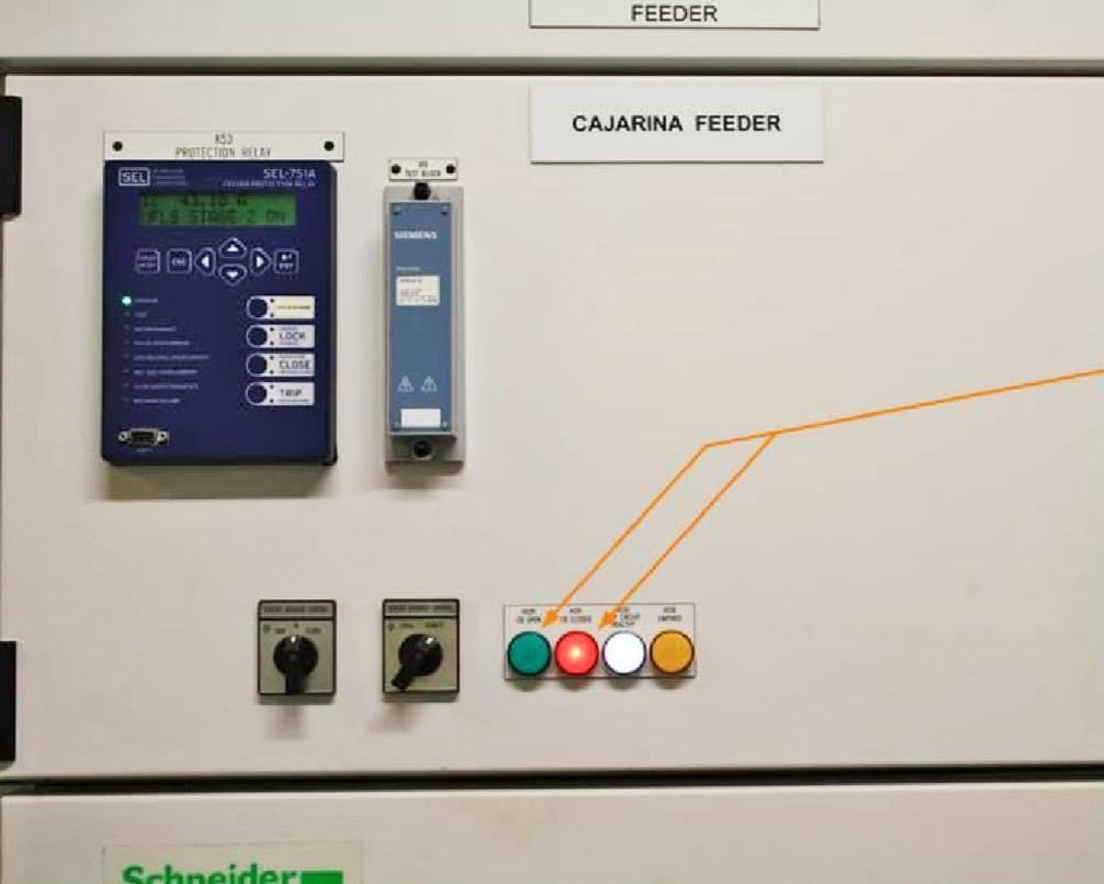
Circuit energisation status indicator are usually provided to show the present energisation state of the cable. The switching operator must confirm the indicator is working when energised and the indicator shows the de-energised state before closing the circuit earth switch.
Interlocks ensure the circuit breaker must be racked out before the earth switch can be closed.
| Title: | Transmission Switching Manual For Grid Operators – Horizon Power |
| Format: | |
| Size: | 5.50 MB |
| Pages: | 182 |
| Download: | Right here | Video Courses | Membership | Download Updates |

It is not normal to find any interlocks within a 66kV zone substation.WHY?