System Architecture
When examining the different philosophies of power system operation and protection, one of the main points of consideration was that the information used by both disciplines was the same even though their goals were different. Furthermore, assurance of the accuracy of the measurements taken was paramount to both.

Utilizing the framework set by IEC 61850, a new architecture for substation design based on precise data collection made available throughout the system would improve both services without hindering either.
Since the only real difference in the two disciplines is software, their hardware sets could be merged into a centralized protection and control (CPC) device that would allow both disciplines to coordinate more readily.
The Merging Unit
CTs and VTs become less accurate as multiple devices are connected to them. Ideally, the CT would be measured by a device with zero impedance, but in reality this is an impossibility. Instead, engineers aim to design the circuit to have as low of an impedance as possible.
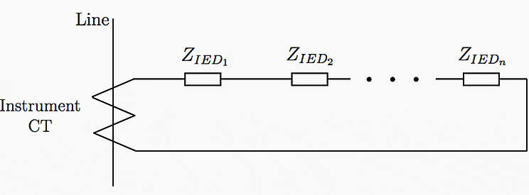
Since these devices must be wired in series to make accurate measurements, illustrated in Figure 1, the overall impedance across the CT grows as more devices are connected.

Ultimately, this increased impedance creates an undesired voltage on the secondary winding of the CT which can lead to the core of the CT becoming saturated during fault conditions. The consequence of this saturated core is that the relationship between the primary and secondary winding currents become nonlinear, and the current being measured is not an accurate representation of the actual system current.
VTs have a similar problem when a large number of measurement devices are connected to them. Opposite to CTs, VTs are ideally measured by a device with infinite impedance, appearing as an open circuit, which is not feasible.
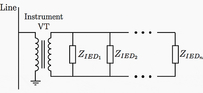
To measure the transformer voltage, devices must be connected in parallel as illustrated in Figure 2.

Determining the total impedance of devices connected in parallel isn’t as straight forward as when they are connected in series; the following formula is used to make this calculation:

The outcome of this relationship is that the more impedances connected in parallel, the lower the equivalent impedance becomes. This lowered impedance results in an undesired current flow on the secondary side, and the series leakage of the transformer introduces a change in voltage on the secondary winding. This voltage is an inaccurate representation of the primary winding voltage, increasing the operation error of the transformer.
Signal flow of this concept is illustrated in Figure 3.
Designing these sensors to be an appropriate impedance would ensure the accuracy of system measurements that can not be offered by the current system.

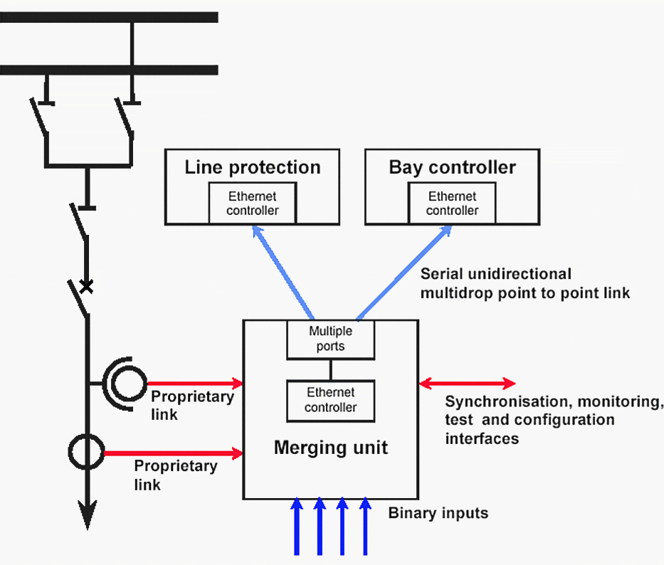
As this device would replace the front end of current IEDs, it could easily be installed in the control house using the existing wiring and connections. Illustrated in Figure 4, such a device has been name a Merging Unit (MU) as defined in IEC 61850-9-1:
Merging unit: interface unit that accepts multiple analogue CT/VT and binary inputs and produces multiple time synchronized serial unidirectional multi-drop digital point to point outputs to provide data communication via the logical interfaces 4 and 5.

The logical interfaces (IFs) referenced in this definition are defined in the standard as well and refer to interfaces that enable the exchange of sample data (IF4) and control{data (IF5) between the process and bay levels. This means that the MU not only acts as a front end to the sensors, but also as a status and control interface for primary system equipment such as circuit breakers, power transformers, and isolators.
These units are synchronized to a GPS receiver using PTP, or newer hardware layer time stamping, resulting in all output sampled values having the same UTC(NTSC) time stamp.
As of this document, there is an implementation agreement for the sampling rates of MUs of 80 samples per cycle for basic protection and monitoring, and a higher rate of 256 samples per cycle for applications like power quality and high-resolution oscillography. At a system frequency of 60 Hz, this results in a sample rate of 4:8 kHz and 15:36 kHz, respectively.
Using this standard, even the slower of the two sample rates is able to detect up to the 40th order system harmonics and measure transients less than a half of a millisecond in duration.
This fidelity far surpasses that of SCADA or electromechanical devices and enables modern digital devices to monitor and record system information of events that may have otherwise gone unseen.
| Title: | Centralized protection and control in digital substations – Adam Thompson at the Faculty of Virginia Polytechnic Institute and State University |
| Format: | |
| Size: | 2.9 MB |
| Pages: | 52 |
| Download: | Here 🔗 (Get Premium Membership) | Video Courses | Download Updates |


Slight clarifications are needed ..
CTs do not become more inaccurate with increasing burdens … P class CTs remain within accuracy limit up to the Accuracy Limit Factor provided the total burden is less than the Rated Burden.
There is not an undesired voltage on the secondary of the CT .. it is essential simply due to Ohm’s Law. The overall objective is to make sure that the “internal voltage” of the CT is sufficient to drive the max fault current through the CT winding resistance plus the connected burden without that voltage exceeding the Kneepoint of the CT.
Note IEC 61850-9-1 has been completely withdrawn in 2011.
The Merging Unit is defined in IEC 61850-2 as “physical unit performing the time coherent combination of the current and/or voltage data coming from sensors” and produces the Sampled Value message.
MU does not specifically have Binary Inputs or Outputs, although some manufacturers provide such options which use GOOSE/MMS messages.
The 80 and 256 samples per cycle was a interim industry Guideline reference for CT and VT Sampled Value MUs which is now defunct since 2016 due to the official Standard for CT and VT as IEC 61869-9 defining 4800/14400/96000 samples PER SECOND (not system frequency dependant).
PTP synchronises the MU, but the SV message does NOT use a UTC time stamp to synchronise the samples – the samples are numbered in sequence to the start of each synchronised 1-second window.