Characteristics of Current Transformers (CTs)
The current transformer primary is connected in series with the device in which the current is to be measured.

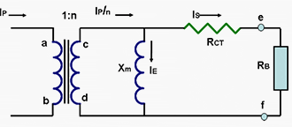
Since current transformer is fundamentally a transformer, it translates the current from the primary to the secondary side, inversely proportional to the turns so as to maintain the relationship:
Ip = n · Is
where, n is the turns ratio of turns between the secondary and primary winding.
Mostly, the primary of a CT is a straight- through bar, meaning the number of turns on the primary is just 1. Hence n is often the number of turns of the secondary.


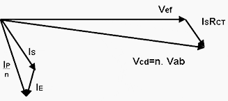
The relationship above is assuming an ideal current transformer without any losses and negligible magnetizing current. In actual practice, the CTs draw a current to keep the iron core excited and drop a voltage proportional to the current transformed because of the inherent resistance of its windings.
The current transformer is expected to deliver about 5A or lower under healthy load conditions. The current goes to a high value if a fault occurs.
As per ANSI, the CT ratio shall be chosen so that the maximum symmetrical fault current on the CT secondary is limited to 100A.
Since it is very difficult to meet the high accuracy requirement for billing purposes near rated current as well as maintain an acceptable linearity for protection at current levels of 100A, it is usual to separate the functions to two different sets of CT cores.
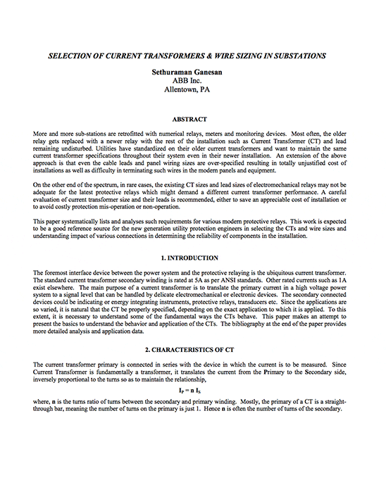
| Title: | Selection of CTs and wire sizing in power substations – Sethuraman Ganesan, ABB Inc. |
| Format: | |
| Size: | 1.38 MB |
| Pages: | 18 |
| Download: | Right here | Video Courses | Membership | Download Updates |


