
33kV Substation Specific Design
The 33kV distribution system of a power supply network is the nearest to the consumer. Consequently, its failures impact customer service more directly than, for instance, faults in the transmission and generation systems, which typically do not result in interruptions to client service. Therefore, the planning of the Fahari distribution system commenced at the customer level.
The demand, kind, location, and other customer load factors were evaluated to determine the most economical distribution system. The substation capacity was determined using the total load adjusted by an appropriate diversity factor.
A long-range time scale with a 25-year horizon was integrated into the design, alongside the associated loads. The customer loads were subsequently consolidated for service from 415V secondary lines linked to distribution transformers that reduce the 11kV primary voltage.
The types and sizes of conductors were subsequently established, with load current and fault level as the primary factors.
A one-line diagram was created, and fault calculations were conducted as a preliminary requirement for the design of the protection system, which was subsequently simulated using ETAP power system simulation software to evaluate the design’s integrity.
33/11 kV Substation Equipment
The substation would be a combination of switching, controlling, and voltage step-down equipment arranged to reduce sub-transmission voltage to primary distribution voltage for residential, commercial, and industrial loads.
Power substation consists of:
- Switchgear: isolators, circuit breakers, earthing switches etc.
- Controlgear: current transformers, voltage transformers, contactors etc.
- Protection equipment: relays, fuses, surge arrestors etc.
- Power Transformers
Substation equipment
The main equipment in Fahari substation consist of:
Transformers:
To step down the 33kV primary voltage to 11kV suitable for distribution purpose. One 33kV/0.415 auxiliary transformer was also needed to supply the substation with reliable AC power.
Circuit breakers:
Circuit breakers were needed so as to disconnect and isolate the faulted section. Sulphur-hexa-fluoride (SF6) circuit breakers were chosen.
Isolating switches (isolators):
It is a requirement that whenever maintenance or repair work is to be carried out on equipment in a substation or feeders, it be disconnected from the supply by an isolator, normally operated on no load.
Isolators are normally interlocked with circuit breakers and earthing switches.
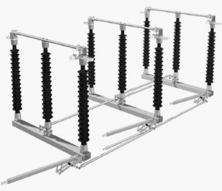
Figure 1 – Rotating centre post disconnector with grounding switch
Current and potential transformers:
Current and voltage transformers were needed so as to step down the line current for the purpose of metering and relaying.
Busbars:
The incoming and outgoing circuits were connected to busbars. Flexible ACSR stranded conductor bus bars supported from two ends by strain insulators was chosen for the 33kV busbar.
Protective relays:
Whenever a fault occurs the protective relay would operate and send a trip signal to circuit breakers. The relays were housed in panels in the control room and Ring Main Units.
Further Study – The art of fault clearance in transmission systems: The logic of main and backup relays
The art of fault clearance in transmission systems: The logic of main and backup relays
Surge arrestors (lightning arrestors):
Surge arrestors would protect the substation equipment from lightning and switching surges.
Earthing switch:
The earthing switch is usually connected between the line conductor and earth and is mounted on the frame of isolator. Normally it is in open position. When the line is disconnected the earthing switch is closed to discharge the trapped charges to earth.
Station earthing system:
The function of station earthing system is to provide a low resistance path for flow of earth fault currents (for proper operation of protection devices) and safety of equipment and personnel.
33kV Substation Feeders
Chosen feeder system was the loop type. Feeders were paired so as to form a closed ring and with each fitted with a circuit breaker. The 11 kV bus was sectionalized into two sections each being fed from the different power transformers.
Each one of the feeders constituting a pair was to emanate from one of these sections and the other from the other section because of the following reasons:
- In case protection system isolates one section of the bus (i.e. if it is faulted) supply is still maintained to the entire loop.
- If one transformer is out, the ring can still be fed from both sides which normally reduces line losses and improves on the voltage regulation.
- It allows for maintenance on any of the switchgear, control gear, transformer etc. without interrupting service to the power consumers.
Tapings from the ring main were designed to be via ring main units which would then feed their respective secondary distribution transformers.
The ring main units are also usually fitted with the necessary switchgear and controlgear as shown in Figure 2.
Figure 2 – Ring system implementation
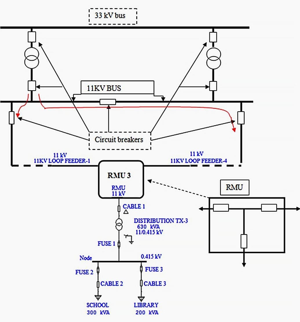
This system is by far the most reliable for continuity of supply and gives better voltage regulation and less power losses. It is used where continuity of supply is the priority factor and thus large investment may be warranted.
Number of feeders
Normally a primary distribution line or feeder is designed to carry a load of 1-4 MVA depending on the feeder length, so the number of Feeders emanating from a secondary substation at 11 kV is 3 or more.
Each feeder was first assigned an average capacity of 2.5 MVA and the substation capacity being the sum of the ONAF ratings of the two power transformers.
| Title: | Design for 33/11 kV power substation, distribution and protection in city of Nairobi – Cyrus Kariuki Kamau At University Of Nairobi Faculty Of Engineering Department Of Electrical And Information Engineering |
| Format: | |
| Size: | 7.20 MB |
| Pages: | 97 |
| Download: | Right here | Video Courses | Membership | Download Updates |

thanks for the explanation
QUOTATION FOR 11kV Transformer Incomer Panels for the 33/11kV L85
MINE IS A QUESTION REGARDING THE OVERVOLTAGE PROTECTION SETTING AT MY PLACE OF WORK INVOLVING A 33KV/11KV TRANSFORMER(10MVA). RIGHT NOW ITS AT 36KV WITH 60 SECONDS DELAY TIME, BUT CHALLENGE IS WHENEVER IT GOES EVEN HIGHER THAN 36KV,IT STILL TAKES THE SAME DELAY TRIP TIME. SO,OTHER THAN THIS SETTING WHAT EXACTLY IS THE BEST INSTATENEOUS SETTING CAN YOU SUGGEST ?
We want to install 66/33 kv and 33/11 kv substation to meet our additional demand. For the same I was reading your design. Thanks for providing such good information
WHAT WORK IS DONE IN THE YEARLY SCHEDULED MAINTENANCE OF A 33/11 KVA SUBSTATION. PL SPECIFY THE QUALITY OF TRANSFORMER OIL TO BE REFILLED. WHAT LIFE IS EXPECTED FOR A SURGE ARRESTOR, 5-10-15 YEARS AFTER FIRST COMMISSIONING?
I need electrical engineer sub station book
This was an insightful document. Thank you.
After subscribing I still can’t get the PDF file.
What do you mean by “can’t get the PDF file”? Just click on the link “Right here” and the download will start.
we are using 33 Kv Crossover coils on HV side Lv is 433 Volts.
My question is in delta connection what is the size conductor we can use for line end and what is standards refer to the tapping leads size conductor.
Good
Hello Sir/Medam
I need this PDF file ??
i need a 33/11 kv indoor substation building lay out and complete study,please help me,mail id:[email protected]
I need 33kv substation material urgent plz
Detailed study for 33/11 kV substation but it would be good if formulas are included here in the explanation.
wish to get some technical support in elect. engg
it is good
thanks
Hello Sir/Medam
Why are you not giving an equation in PDF file ??
I want all the equation which is not shown in PDF file of Design study for 33/11 kV substation, distribution and protection in the city of Kenya so what can I do??
Please i need design equations, thanks
It’s very nicely explain.I love to read your portal .
Thanks & Regards,
Santosh Salunke.
The portal itself is so useful and it goes along with me everywhere …
It is nice for students to see the real implementation of what they study.
that is why the formulas are needed if possible,
All the formulas in the file are deleted :)
it’s worfless without the formulas!! Can you upload the original Word .docx document!!?
Maybe need to register the membership to unlock all information…..
1. Is earth switch necessary in distribution line? Briefly explain you answer with necessary
logic?
2. Can the Earth Switch, Isolator and Circuit Breaker be closed at a time? Explain the
reason behind your answer.