Earth Resistance for Electrical Grounding Systems
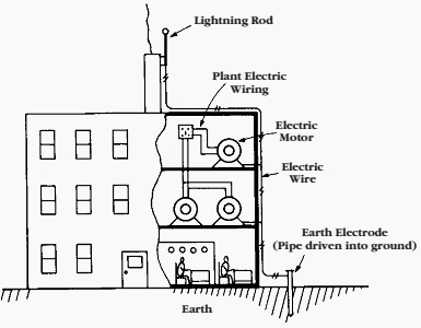
The simplest and somewhat misleading idea of a good ground for an electrical system is a section of iron pipe driven into the earth with a wire conductor connected from the pipe to the electrical circuit (Figure 1).

This may, or may not, be a suitable low resistance path for electric current to protect personnel and equipment.

A practical earth electrode that provides a low ground resistance is not always easy to obtain. But from experience gained by others you can learn how to set up a reliable system and how to check the resistance value with reasonable accuracy.
The principles and methods of earth resistance testing covered in this section apply to lightning arrester installations as well as to other systems that require low resistance ground connections. Such tests are made in power-generating stations, electrical-distribution systems, industrial plants, and telecommunication systems.
Factors That Can Change Your Minimum Earth Resistance
We will discuss later what value of earth resistance is considered low enough. You’ll see that there is no general rule usable for all cases.
First, however, consider following factors that can change the earth electrode requirements from year to year:
Rule no.1
A plant or other electrical facility can expand in size. Also, new plants continue to be built larger and larger. Such changes create different needs in the earth electrode. What was formerly a suitably low earth resistance can become an obsolete “standard.”
Rule no.2
As facilities add more modern sensitive computer-controlled equipment, the problems of electrical noise is magnified. Noise that would not effect cruder, older equipment can cause daily problems with new equipment.
Rule no.3
As more nonmetallic pipes and conduits are installed underground, such installations become less and less dependable as effective, low resistance ground connections.
Rule no.4
In many locations, the water table is gradually falling. In a year or so, earth electrode systems that formerly were effective may end up in dry earth of high resistance.
Factors Influencing Requirements for a Good Grounding System
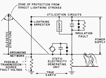
In an industrial plant or other facility that requires a grounding system, one of the following must be carefully considered (see Figure 2):

Limiting to definite values the voltage to earth of the entire electrical system. Use of a suitable grounding system can do this by maintaining some point in the circuit at earth potential.
Such a grounding system provides these advantages:
- Limits voltage to which the system-to-ground insulation is subjected, thereby more definitely fixing the insulation rating.
- Limits the system-to-ground or system-to-frame voltage to values safe for personnel.
- Provides a relatively stable system with a minimum of transient overvoltages.
- Permits any system fault to ground to be quickly isolated.
| Title: | A Practical Guide To Earth Resistance Testing – Megger |
| Format: | |
| Size: | 1.5 MB |
| Pages: | 41 |
| Download: | Right here | Video Courses | Membership | Download Updates |


How to do earth testing using Top Tronic resistance tester on substation?
Thanks for the guide
Many thanks for your articles. It’s a technical brief for me in this subject.
Regard.
M.Khalil
I need to know what I have to do first for earth resistance in earth rod.
*Do I need to disconnect earth cable from earth rod before measuring earth rod
1) HV substation
2) Power house
3) Homes
I would be thankful to you for your continuous useful information to me which are all very useful to my knowledge upgradation and I wish you to keep it up better.
Thanks