
Earthing system
The project of earthing system is prepared in accordance with the requirements of the investor and Standard: IEEE 80 –2000 Guide for Safety in Substation Grounding. Specific resistance is calculated on the basis of measured values of soil resistivity. The earthing system is designed so that the allowable touch and step voltages do not be exceeded.

The calculation is done using the software CDEG MultiGround TM SES – Safe Engineering Services & technologies ltd. Canada whose results are shown in Appendices. The result shows that the touch and step voltages are within the permissible limits.
Soil resistivity measurements
Document already exists and it is Expected Soill Resistivity Study of Bazian Steal Factory S/S-132/11kV, 1×30/40MVA. That document should be placed here (suggested). The measured resistance values at particular site as well as computed output of soil resistivity results are enclosed in Appendices 1 to 4.
Earthing Calculation Details to IEEE Std. 80-2000
Grid Conductor Sizing
Required minimum earth grid conductor size:
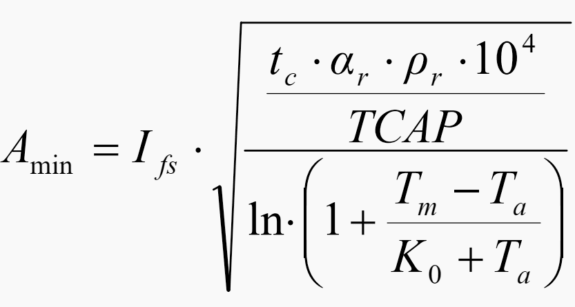
Where:
- Single pole short circuit current: Ifs = 31,5 kA
- Duration of fault current: tc = 0,5 s
- Thermal resistivity coefficient at the referent temperature (20°C): αr= 0,00381 1/ ˚C
- Resistivity of the grounding conductor at the referent soil temperature: ρr= 1,78 μΩ·cm
- Thermal capacity of copper: TCAP=3,42J/cm3/˚C
- Max allowable temperature for brazed joint: Tm = 1084 ˚C
- Ambient temperature: Ta = 40 ˚C
- Ko=1/Ao at 0°C, K0 = 235
Therefore:
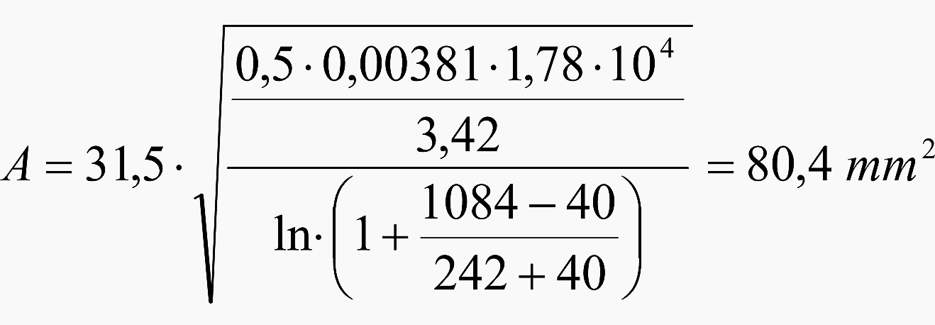
Important Note! – According to customer’s specification earth grid conductor shall not be less than 120 sqmm, therefore the earth grid conductor size to be used is 120 sqmm.
Calculation of current flowing between ground grid and earth
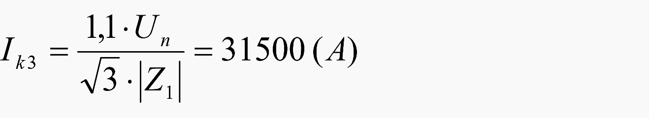
Where:
- Symmetrical three phase short-circuit current (r.m.s.): Ik3=31.5 kA
- Nominal system voltage: Un=132 kV
- Positive sequence impedance at the fault location: Z1
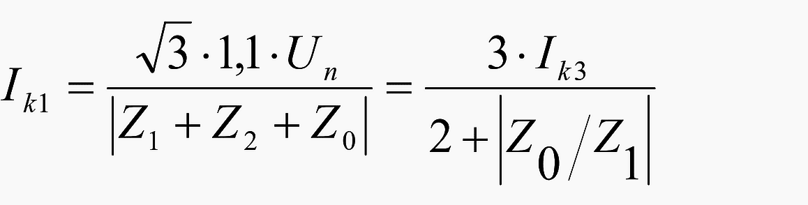
- Single phase to earth fault current Ik
- Ratio of zero-sequence impedance to positive sequence impedance to network as viewed from fault location in case of solidly earthed neutral |Z0/Z1|=3
Therefore,
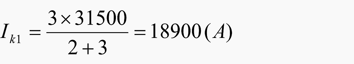
![]()
Where:
- Grid current discharged into grounding system: Ig
- Current division dactor that flows between ground grid and surrounding earth: SF=0,6
- Phase to earth fault current: Ik1=18900 (kA)
Therefore, grid current: Ig = 0,6×18900 = 11350 (A)
Tolerable Step and Touch Voltages
Reduction Factor Due to Resistivity of Crush Rock Surface
120 mm thick layer of crushed rock is spread on the earth’s surface above ground grid in the switchyard to increase the contact resistance between the soil and the feet of the personnel in the substation.
Touch and Step Voltage Criteria
The safety of a person depends on preventing the critical amount of shock energy from being absorbed before the fault is cleared and system de-energized. The maximum driving voltage of any accidental circuit should not exceed the limits defined later.
The safe touch and step voltages to be used for verification of grounding design is calculated using MALT engineering module of CDEGS computer program. In the Appendix 7 the computer printouts are presented.
| Title: | Earthing system calculation for 132/11 kV, 1×40 MVA substation of steel factory |
| Format: | |
| Size: | 415 KB |
| Pages: | 29 |
| Download: | Here 🔗 (Get Premium Membership) | Video Courses | Download Updates |

dear thank you all that you have been given me information and
Information is useful.
We need the flow of grid current in diagram also.
Good information and useful
I have problem in my grid station circulating current in 40 Mva power transformer increased upto 6 amp in body as well as in mesh also how decreased
Felicitaciones !!, muy buen articulo para entender desde el punto de vista seguridad en proyectos eléctricos
Hello dear sir!
Thank you so much for deep knowledges you’ve been feeding us. It’s very helpful
dear Sir,
Thank you very much for information on EEP . The EEP is quit useful.