
132/33 KV EHV substation
The project work assigned to us was to design a 132/33 KV EHV substation. We considered incoming power at 132 KV and the power was transferred to main bus through isolator-circuit breaker-isolator combination. The power from main bus was fed into a 20MVA transformer which stepped the voltage down to 33KV.
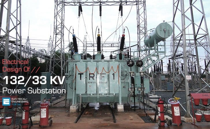
The power is then fed into a 33KV bus from which different loads were tapped. In the process, the surge impedance loading of 132 KV and 33 KV lines were calculated and they were used to estimate the maximum power that can be transferred by one transmission line.
The design of the entire substation was made keeping in mind the most basic requirements of a proper substation including the civil and domestic requirements.
The power factor is corrected here and the voltage is stepped down to 33KV and power is then transferred to distribution system of the grid to meet the requirements of the end consumers at their suitable voltage.
Figure 1 – 132-33 kV substation single line diagram
A Design Layout Of 132/33 Kv, 200 Mw Substation
The substation is linked to three substations or loads: A (3.2 MW), B (3.2 MW), and C (3.2 MW) at 33 kV, and D (36 MW) at 132 kV. The produced 16.2 kV is stepped up to 132 kV and transmitted to the 132 kV substation via two double circuit transmission lines.
Upon evaluating the load requirements and SIL of transmission lines, the entire configuration is organized as follows:
Our Assumptions
- The value of surge impedance of transmission lines under consideration = 325 Ω
- Total load requirement = 3.2 MW + 3.2 MW + 3.2 MW + 36 MW
- The distance between the substation & the neighboring generating station is 50km
The SIL of 132 KV line = (132KV) 2/325 = 53.61 = 54 MW (approximately)
The SIL of 33 KV line = (33KV) 2/325 = 3.35 = 3.5 MW (approximately)
Given that the distance between the substation and the generating station is merely 50 km, the SIL may augment to 1.2 times the theoretical value. Consequently, the substation’s intake may reach up to (108 X 1.2) MW, around 130 MW.
Figure 2 – Curve delivered power / Transmission distance
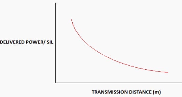
The curve is highly relevant for assessing transmission line loading concerning transient and steady-state stability for operating voltages ranging from 66 to 500 kV. For loads A, B, and C, it is appropriate to reduce the incoming 132 kV voltage to 33 kV.
Therefore, power transformers with a rating of 132/33 kV and 20 MVA are utilized. A duplicate transfer of identical rating is erected to accommodate anticipated future demand increases.
The 33KV is subsequently reduced to 11KV and ultimately to 440V to satisfy the requirements of local station loads.A transfer bus is incorporated into the system to facilitate the maintenance of the main bus.
Insulation Coordination
Insulation coordination is the process of establishing appropriate insulation levels for various components within a power system, together with their configurations. The selection of an insulation structure capable of withstanding the voltage strains imposed on the system or equipment, along with the appropriate surge arrester, is essential.
The technique is ascertained from the established attributes of voltage surges and the specifications of the surge arrester.
Optimized refers to achieving the most favorable economic equilibrium among numerous parameters based on this coordination: n cost of insulation, n cost of protective devices, n cost of failures relative to their probability.
Further Study – Insulation coordination study for lightning overvoltages in 420 kV power substation
Insulation coordination study for lightning overvoltages in 420 kV power substation
Busbar Design
Busbars are copper or aluminum rods made of thin-walled tubes that function at a constant voltage. The busbars are engineered to constantly conduct standard current. The cross-section of conductors is determined based on the rated normal current and the following factors: system voltage, substation location, flexibility, supply reliability, and cost.
Our design must facilitate straightforward and continuous maintenance, eliminating any risk to the safety of operational people. It should have a straightforward architecture and provide the capability for future expansion. Any variation in load must not impede its mechanical properties.
The busbars at a substation are often categorized into three distinct types:
- Outdoor rigid tubular bus-bars.
- Outdoor flexible ACSR or Al alloy busbars.
- Indoor busbars.
Our substation employs a configuration of one main bus and one transfer bus system. The buses are interconnected via a bus coupler that enables load transfer during maintenance and fault scenarios.
| Title: | Design of 132/33KV Substation – Sudipta Sen, Arindam Chatterjee and Debanjan Sarkar // IJCER – International Journal of Computational Engineering Research |
| Format: | |
| Size: | 456 KB |
| Pages: | 13 |
| Download: | Here 🔗 (Get Premium Membership) | Video Courses | Download Updates |
Further Study – Interlocking for 380kV GIS Substation: Insights into CB and isolator test and service positions
Interlocking for 380kV GIS Substation: Insights into CB and isolator test and service positions

I am doing my final year design project. I have 11 kV system with eight mini-substations. The mini-substation are indicated in kVA ranging from 200 to 500. I am using DIgSilent to draw the schematic. My question is how do I represent the mini-substation on the software.
I’ve sent to your Company a few questions earlier today.
What I’d also like to know, how often do they breakdown ?
Our substations are either being sabotaged or not repaired in the correct way.
Today we’ve had very little power supply to many areas in Pietermaritzburg – at this moment we either have loadshedding again or more repairs done to the substation. Our power is OFF!
Here is another notice received later this evening regarding the faulty subtation.
*Primary Substation Update*
Date: 09/03/2023
Time: 21h45
*Riverside Primary Repairs*
1. 132/33kV Transformer 2 fault at Riverside Primary.
*Affected equipment*
132/33kv Transformer 2
*Affected areas*
City East, Manor, Willowton industrial, Mountainrise, Eastwood, Panorama Gardens, Glenwood, Cinderella, Tamboville, thembalihle, Madiba, Sobantu, Willowton, Wensleydale, Parts of Pelham, Scottsville, Hayfields, Lincoln Meade, Hollingwood, Parts of Bishopstowe, Epworth, Parts of Oribi, Parts of Bisley and surrounding areas
*Corrective Action*
Initiating repairs.
NB: Load Reduction has been implemented in order to protect the Transformer currently in operation.
*Stages to completed*
1. Arrange Resources ✅
2. Arrange Materials in progress✅.
3. Assemble Circuit ✅
4. Erection and installation of 132kv Circuit Breaker ✅
5. Erection of CB poles (Shutdown required)✅
6. Terminating and clamping to the busbar ( Shutdown required) ✅
7. Install and laying of control & Protection cabling is in progress.
8. Testing and Commissioning
9. Energize
Apologies for any inconvenience caused by this crisis
We as a Community of Mzunduzi Municipality would like to know if this is sabotage or genuine faults being experienced by the substation supplying us in Pietermaritzburg?
CAN YOU SEND TO ME TECHNICAL SPECIFICATION FOR 132/33KV MOBILE TRANSFORMER CAPACITY 20 MV
BEST REGARD
ENG. YASIN ABBAS
why usually used the letter E for 132kv cubicles and H for 33kv cubicles and the letter L or AL for 6.6kv cubicles?
I am electrical engineer
I wana to learn,read,about power system and i got some good tips about power system form this port