
Transformer Testing
This guide is to be understood as a supportive guide, giving a summary about applied electrical measurements. These electrical tests are essential to estimate and verify the specifications and the dielectric strength of the transformer. It also provides the sense of manufacturer’s internal quality protection and aspiration of constructing a valuable product.
Although some calculations are necessary for preparing and analysing the measurements, we are not considering the matter of scientific approach or any mathematical explanations.
The essential content is to inform and give formal explanations by means of basic formulas.
Followed by chapters with descriptions of each measurement, the initial chapters cover the issue of relevant Standards and dielectric integrity in general, simplifying the area of testing high voltage devices, such as power transformers.
1. Voltage stresses and dielectric integrity
1.1 General
During their operating time, transformers are exposed to several voltage stresses, which can appear during normal as well as abnormal operation. In general, over-voltages are distinguished into three categories:
- Lightning over-voltages (A) – with a duration in the order of microseconds
- Switching over-voltages (B) – with a duration in the order of a fraction of a second
- Over-voltages (C) – with a duration in the order of seconds to minutes
Figure 1 – Types of overvoltages transformers are exposed to

Dielectric tests are intended to verify transformers integrity in case of over-voltages, as described above. The different groups of over-voltages have also been considered in a test code. The actual test code for a particular object, which is specified by a Standard, depends primarily on the size and rated voltages of the object.
Test voltages are primarily sinusoidal AC voltages. DC voltages are usually only relevant for valve transformers, like HVDC transformers.
Later on it was found that other voltage shapes, which includes transient impulse voltages (e.g. switching- or lightning over-voltages), are more suitable to describe the stresses during abnormal conditions like lightning strikes.
Through the evolution of electronic diagnostic tools, more tests were added, those like the measurement of partial discharges, which has become indispensable nowadays.
Table 1 – IEC/IEEE standards related to transformer routine tests
| Standard | Section/Clause | Type of test |
| IEC | 60076-3 Power transformers – Part 3: “Insulation levels, dielectric tests and external clearances in air” | Routine tests |
| IEEE | C57.12.90 Standard Test Code for Liquid-Immersed Distribution, Power and Regulating Transformers, Clause 10: “Dielectric tests” | |
| C57.12.00 General Requirements for Liquid-Immersed Distribution, Power, and Regulating Transformers |
1.1.1 Lightning over-voltages
Lightning over-voltages are caused by weather-related, atmospheric discharges. The power of the over-voltage in the grid depends on the lightning current and the impedance at the strike location.
The typical wave form of a lightning over-voltage can be seen in Figure 2.
This wave is unipolar (only one polarity) and propagates along the line, starting at the location of the voltage strike. It increases to a peak within a few microseconds (wave front, distinctive: high surge) and decays back to zero within about a hundred microseconds (wave tail).
The insertion of those protective devices may conversely cause a steep voltage breakdown, which can be seen as a chopped lightning impulse at the transformer terminal.
Figure 2 – Lightning over-voltages
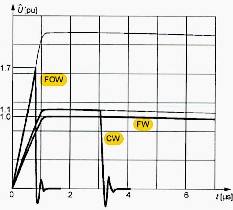
Where:
- FW = full wave
- CW = in tail chopped wave
- FOW = in front chopped wave
1.1.2 Switching over-voltages
Switching operations cause transient phenomena, what can lead to over-voltages. Shape, duration and amplitude depending on the grid’s configuration and point of switching operation related to sinus wave.
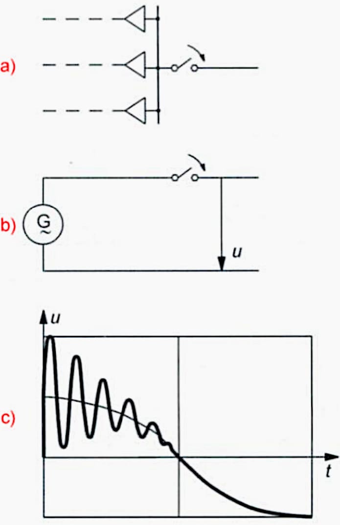
Figure 3 shows an example of an over-voltage, during a switching operation in an overhead line.
- Configuration of network
- Equivalent diagram
- Oscillogram of switching impulse voltage
Figure 3 – Switching over-voltages
1.1.3 Temporary over-voltages
Temporary operating and non-operating over-voltages are caused by the following:
- Load rejection: over-voltage of 1,1 to 1,4 pu (several seconds),
- Single-phase short-circuit: over-voltage of 1,2 to 1,7 pu (depending on neutral point configuration),
- Ferro resonance (saw-tooth oscillations),
- Ferranti-effect,
- Other resonance oscillations.
2. Transformer’s insulation verification
Figure 4 shows the relationship of the withstand voltage of conductor insulation to earth and the duration of the over-voltage. Curve I and II represent the general behaviour of the major insulation to earth in the area of impulse- and temporary overvoltages.
Each area is specified in duration and magnitude.
- A: Lightning impulse overvoltage
- B: Switching impulse overvoltage
- C: temporary overvoltage
Figure 4 – transformer insulation levels
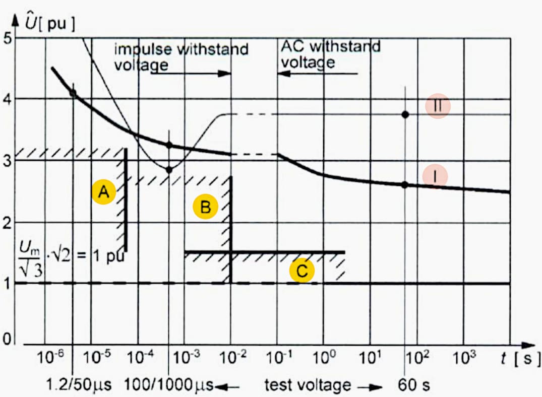
- Diagram I: Oil insulation
- Diagram II: Air insulation
For each area (A/B/C) tests are specified, verifying the impulse and AC withstand voltage of the Transformer. The magnitude of the three test voltages depends on the highest voltage for equipment Um and is defined in IEC and IEEE. For a comparison diagram I & II show the withstand voltage characteristics of oil and air insulated transformers.
It should be mentioned that a significant decrease in withstand voltage in the area of switching over-voltages occurs.
If the transformer exceeds or runs close to its major insulation level, the operating life time may be decreased.
3. Test voltages
3.1 Alternating voltages
Regarding the standards, an alternating test voltage may either consist of a voltage electrically energizing a circuit called a separate source, or a voltage across two terminals of a winding, needed to conduct a test called an Induced voltage test. The duration of the alternating test voltage has been traditionally 60 seconds, which is called “one-minute test” at low frequency (close to the rated frequency).
For voltages substantially above rated value during an induced voltage test, the core will saturate unless frequency is increased in proportion.
The switching impulse is then considered crucially for insulation integrity, while the level of partial discharges is a qualitative measure of the insulation.
Suggested Guide – Electrical Testing and Commissioning Handbook
3.2 Impulse voltages
As seen in section: 3.1, there are actually two different types of transient impulse voltages: The Lightning impulse with a “short” duration and the Switching impulse with a “long” duration. The Lightning impulse is characterized by a steep voltage rise and a fast decay. On the other hand, the switching impulse possesses a longer duration for wave front and –tail.
The total duration of the switching impulse is generally ten to twenty times longer than the lightning impulse.
The wave characteristics of the winding have to be considered. For a switching impulse the rate of change in voltage is low enough to permit a model where wave characteristics can be ignored and transformer behaviour is similar to that under normal AC voltage and power frequency conditions.
Figure 5 – Two tests fields performed on a power transformer
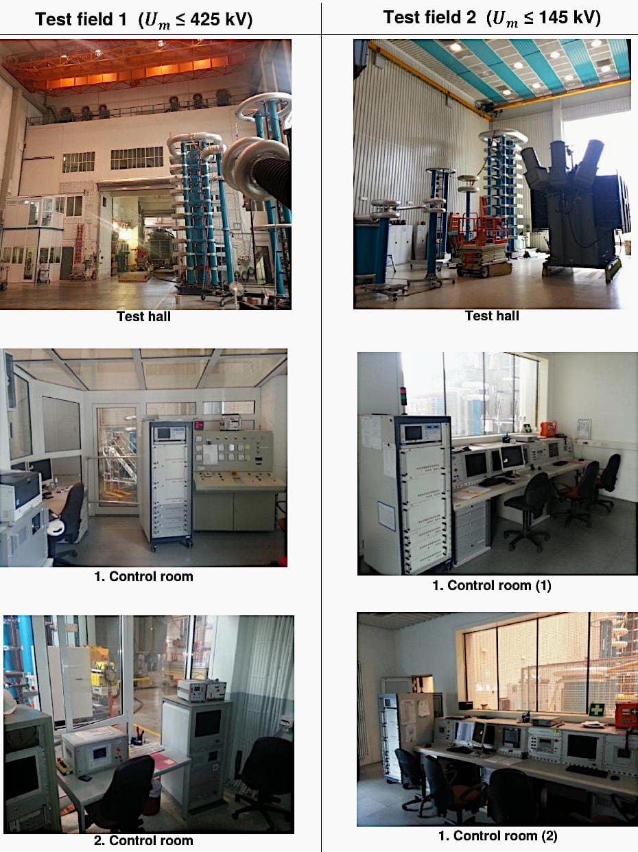
Test field 1 is used as the routine test field for almost every measurement. Because of its larger dimensions (distances to walls etc.), it is allowed to conduct measurements with higher voltages than test field 2.
Test field 2 is feasible for transformer with less rated voltages. Because of small distances to the walls, lightning impulse tests are limited to values where no flash overs will occur.
3.3 Digital measuring systems
Digital measuring systems are used for measuring and displaying impulse voltage and current waves as well as AC transients, evaluating impulse parameters for peak voltage, current and time.
By means of an analyzing system, test results are stored to a database for evaluation and comparison from different tests.
- Power and instrument transformer controls
- AC Resonant test system (HighVolt)
- Impulse voltage test system “MIAS” (HighVolt)
To cover all electric measurements, further devices like AC/DC Peak voltmeter, instrument transformer controls etc. are installed. In fact there are also portable measuring devices (e.g. winding resistance meters, voltage ratio meter, etc.), which are not placed in control rooms.
| Title: | Beginner’s Guide to Electrical Testing of Power Transformers – Siemens |
| Format: | |
| Size: | 5.10 MB |
| Pages: | 117 |
| Download: | Here 🔗 (Get Premium Membership) | Video Courses | Download Updates |
Suggested Study – Practical guide to smart substation automation in electric energy distribution
Practical guide to smart substation automation in electric energy distribution
