
Maintenance and testing
With ever growing demand for power, it is not uncommon for transmission utilities to build and operate substations at High Voltage (HV) and Extra High Voltage (EHV) levels. Maintenance and testing of assets in EHV stations is critical for proper electric power grid operation and reliability.
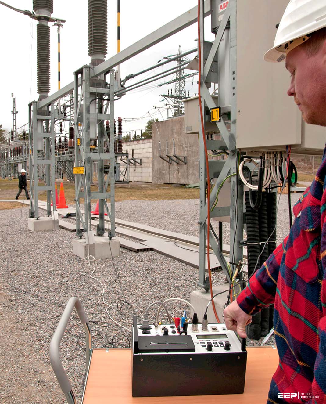
Performing electrical measurements accurately and reliably in such environments is always a challenge because of the presence of unwanted electrostatic noise and interference. Testing Bushing Current Transformers (BCT) on a transformer or circuit breaker can be especially problematic because of induced voltage on bushing terminals from their proximity to overhead energized lines.
In these high noise environments, tests recommended in IEEE standard C57.13.1 such as ratio, polarity, excitation and DC insulation resistance may suffer from inconsistent and unreliable measurements.
Paper concludes with a case study of testing multiple BCTs on a 765/500/13.8 kV, 750 MVA auto transformer with tertiary in an energized EHV substation in inclement weather condition, where the BCTs were tested with high accuracy and precision despite extreme interference conditions.
Introduction
Current Transformers (CT), DC power supplies, circuit breakers and relays are some of the key components of the protection and control systems.
The reliable operation of a protection system depends to a large extent on the performance of these devices. Any mis-operation of these components may leave the power system in a vulnerable state with the possibility for irreparable damages. Periodic testing of these assets will ensure a protection circuit that would operate when it is called upon.
Testing BCTs can become a challenge when they are under overhead energized lines such that measurements suffer by induced voltage on bushing terminals. This problem gets more pronounced when testing is performed in EHV stations.
This paper attempts to address the issue by first understanding the root cause of the problem, recommending the solution, performing the test as per the recommendations and finally evaluating the results.
IEEE Recommended Tests for Relaying Type CTs
Due to the importance that CTs play in power system protection, the IEEE Power Engineering Society recommends certain field test measures for relaying type CTs. These tests are designed to verify proper operation, connection, and condition of the CTs.
IEEE Standard C57.13.1, “IEEE Guide for Field Testing of Relaying Current Transformers” outlines the intention for the designated tests as well as the test procedures. Following are a list of the recommended tests and measurements.
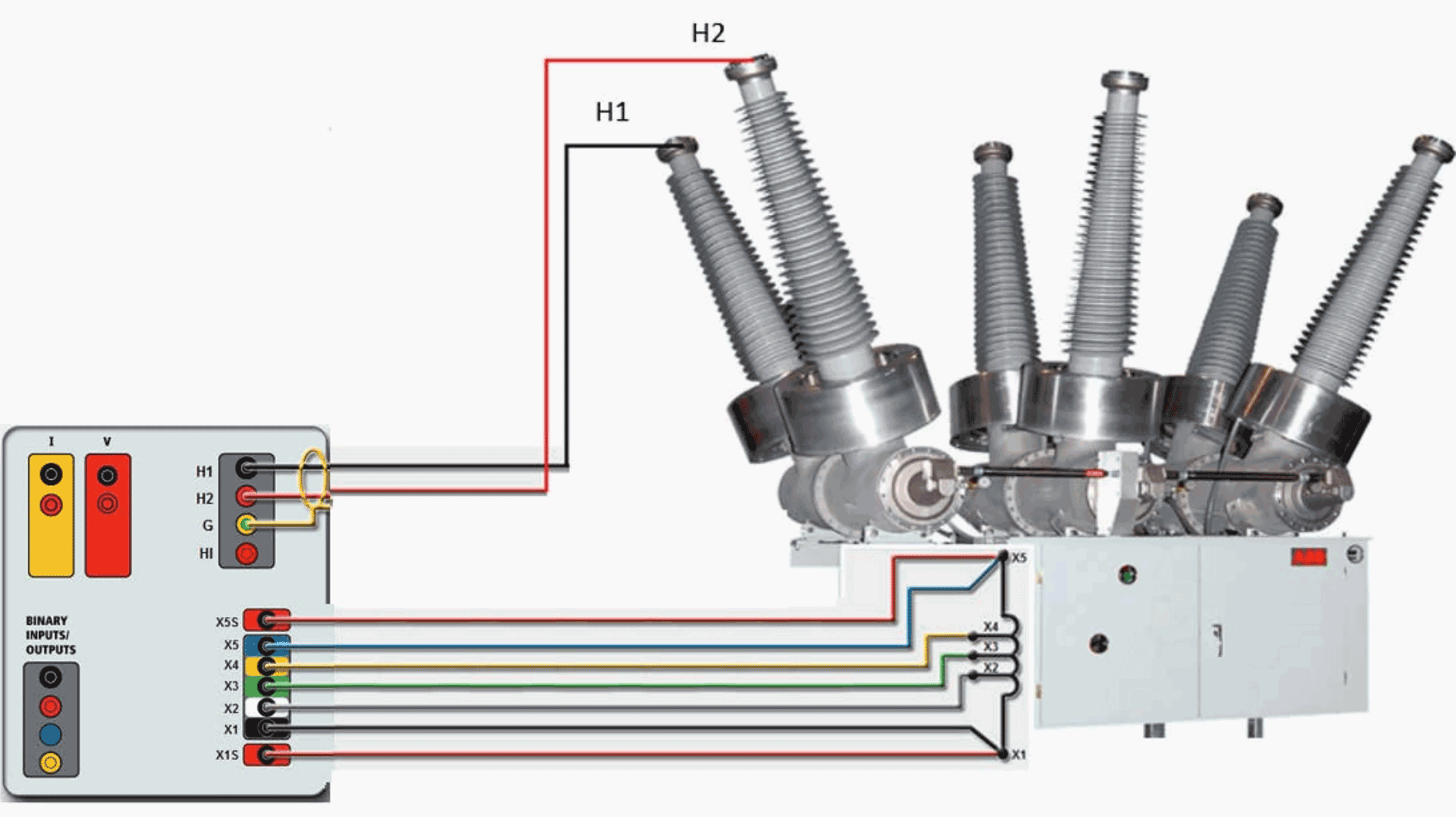
1. Ratio Test:
This test verifies the ratio and connection of the CT, as well as any taps that are available. This can be accomplished with the equipment both in and out of service. The out-of-service voltage method require injecting a voltage into the secondary (V1) and measuring the primary voltage (V2), which will be directly related to the CT turns ratio (N1 / N2).
N1 / N2 = V1 / V2
The in-service current method requires placing ammeters on both the secondary and primary leads and recording the current values. These values will also be directly related to the CT turns ratio.
2. Polarity Test:
This test verifies that the current flow in the secondary matches the designed flow respective to the primary current. This is especially important for CTs being used in differential or comparative relaying.
This can be accomplished in a number of ways including:
- Temporarily applying a DC voltage to either the primary or secondary and verifying analog meter deflection,
- Applying an AC voltage to the secondary and using an oscilloscope to compare with the primary voltage,
- Paralleling a reference CT with the secondary of the test CT and
- Verifying current magnitudes, and measurement of phase angle.
3. Insulation Resistance Test:
This test verifies that the CT insulation is satisfactory between both winding to winding and winding to ground. This is usually performed with an insulation resistance tester.
Three tests are usually performed to check the integrity of the insulation system:
- Primary to ground
- Secondary to ground
- Primary to secondary
4. Resistance Measurement:
This test verifies the DC resistance of the CT secondary winding as well as the connections within and on the equipment. This can be measured using a traditional low resistance ohmmeter or calculated using a DC volt-amp circuit.
5. Excitation Test:
This test verifies the saturation characteristics of the CT and its taps, thereby confirming accuracy ratings, connections, and absence of internal short circuits.
The plot of this measurement is compared to previous data and any deviation should be investigated.
6. Admittance Test:
This test verifies the nearly constant internal and external burden of the CT as it is installed. This is performed by injecting an acoustic signal into the CT and detecting the circuit admittance.
This measurement will be compared to previous system results and any deviation will indicate an abnormal condition.
7. Burden Test:
Part of the rating classification of a CT is its ability to supply a known current into a known burden and meet a stated accuracy. Burden test verifies that the CT can maintain a designated accuracy for a known burden and supplied current.
A rated secondary current is applied to the burden connected to the CT secondary and voltage is measured across it to calculate the impedance and phase angle of the burden. In field, it is very important to verify that the burden of the circuit does not exceed the conditions in which the CT will maintain it specified accuracy and performance.
Any significant drop in current will show that the CT’s designed burden has been exceeded.
| Title: | Performing electrical tests in EHV substations – Dinesh Chhajer, PE (Megger North America) and Dallas, Ian Kreher (American Electric Power Roanoke, VA USA) |
| Format: | |
| Size: | 675.6 KB |
| Pages: | 18 |
| Download: | Right here | Video Courses | Membership | Download Updates |

IT VERY KNOWLEDGABLE
Thanks, the article is very useful for operation/maintenance engineer
I’m impressed with your site, learning and helpful. Appreciations
Very good article
I would like to read such like very important technical papers
Thanks