
Introduction to faults in T&D systems
As you know, faults on electrical transmission and distribution systems can lead to severe economic losses, and that’s not good. Rapid information about the type and the location of the fault can assist the task of repair and maintenance, thereby minimizing the economic effects of power interruption.
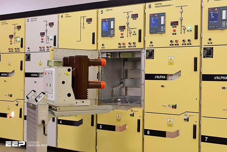
Usually, faults are considered dangerous because of over current that they create. Circuit breaker is a very unique device which is being used widely for the interruption due to occurrence of a fault in the power system.
For the proper selection of circuit breaker it is necessary to find out the maximum fault current that can occur due to a fault in the system.
Thus fault studies need to be routinely performed by utility engineers.
Faults usually occur in a power system due to insulation failure, flashover, physical damage or human error. These faults may either be three phase in nature involving all three phases in a symmetrical manner, or may be asymmetrical where usually only one or two phases may be involved.
Faults may also be caused by either short-circuits to earth or between live conductors, or may be caused by broken conductors in one or more phases.
Sometimes simultaneous faults may occur involving both short-circuit and broken conductor faults (also known as open-circuit faults).
Balanced three phase faults may be analyzed using an equivalent single phase circuit. With asymmetrical three phase faults, the use of symmetrical components help to reduce the complexity of the calculations as transmission lines and components are by and large symmetrical, although the fault may be asymmetrical.
Fault analysis is usually carried out in per-unit quantities (similar to percentage quantities) as they give solutions which are somewhat consistent over different voltage and power ratings, and operate on values of the order of unity.
For the correct application of protection equipment, it is essential to know the fault current distribution throughout the system and the voltages in different parts of the system due to the fault. Further, boundary values of current at any relaying point must be known if the fault is to be cleared with discrimination.
The information normally required for each kind of fault at each relaying point is:
- Maximum fault current
- Minimum fault current
- Maximum through fault current
The most important types of faults are as follows:
- Single-phase to earth
- Phase to phase
- Phase-phase-earth
- Three-phase (with or without earth)
The above faults are described as single shunt faults because they occur at one location and involve a connection between one phase and another or to earth. In addition, the Protection Engineer often studies two other types of fault:
- Single-phase open circuit
- Cross-country fault
By determining the currents and voltages at the fault point, it is possible to define the fault and connect the sequence networks to represent the fault condition. From the initial equations and the network diagram, the nature of the fault currents and voltages in different branches of the system can be determined.
| Title: | Fault current selection for a circuit breaker from a substation layout – Md. Shahadat Hossain, Shahrukh Alam Sakib, S.M. Nomam Siddique and Shawon Paul at the Department of Electrical and Electronic Engineering, Stamford University of Bangladesh |
| Format: | |
| Size: | 1.5 MB |
| Pages: | 69 |
| Download: | Right here | Video Courses | Membership | Download Updates |

Really professional approach with clear explanation. Very useful
Ayyagari
Dear Concern,
Good day. I am an electrical engineer & and successfully installed 30 Nos. of Sub-Stations of different capacity ranging from 0.5 MVA to 2.5 MVA , 11 / 0.415 KV. I am very much interested on the following items.
a. Calculation of symmetrical & assymtrical fault current at the Sub-Station and Load pint.
b. Pickup value setting of the IDMT Relay.
c. Descrimination chart of circuit breakers.
.