
Transformer Thermal Design
The thermal design of the transformer defines the temperature the winding conductor will reach under specific loading conditions. The allowed temperature limit for the transformer depends on the type of insulation and oil used in the transformer. These limits are relevant to determine the capability of the transformer to withstand short and long time overloading conditions.

Both insulation and oil in the transformer have different temperature limits. The insulation limit usually lies between 120 °C and 180 °C, above this range, dielectric failure can occur in insulation due to gas bubble formation. The limit according to IEC standards for the oil usually lies at 98 °C, the temperature at which the aging rate of insulation is considered to be normal.
This second limit determines the rated load of the transformer, at which the transformer can be accepted to carry normal operation throughout its lifetime.
The parameters that determine the thermal characteristics of any given power transformers are as follows:
- The current density in the winding conductor of the transformer expressed in amperes per square mm (A/mm2).
- The thermal resistance of the insulation of the conductor depends on its thickness.
- The flow of the oil and its flow velocity through the conductor.
- The thermal characteristics of the oil and the coolers.
There is no critical temperature for describing the deterioration characteristics of insulation, and temperature standards set up for the transformer rating and operation have to be based on the transformer’s service life experience and to some extent must be within the range of the opinion of the standardizing body.
This standardization of the temperature provides helpful guidelines for transformer operation and a common platform for the comparison of costs and performance characteristics of transformers of different designs and manufacture.
Recommended Reading:
My worst experience in testing and commissioning power transformers (and how I fixed things up)
These days the limiting hottest-spot temperature is set to be 105 °C, for continuous operation of the transformer by standardized bodies. It’s assumed that the average temperature of windings is 10 °C less than the hot-spot temperature at rated load for the transformers. A maximum limit of 95 °C was set for the average temperature as determined by the resistance measurement of the transformer’s windings.
For example in an oil-immersed air-cooled transformer, if the ambient temperature is 40 °C, the permissible temperature rise of the transformer above ambient becomes limited to 55 °C. This 55 °C rise has been accepted as transformers’ standard rating for its continuous operation.
This temperature is also known as the transformer’s operation point which the unit operates without exceeding this temperature rise.
The operation of the transformer with an excellent record very much depends on these above-mentioned facts and operation conditions cannot be accepted at 40 °C ambient temperature with a continuously full load or at a hot-spot temperature of 105 °C. If the 40 °C ambient coincides with continuous rated load, the life of the transformer has been shorter than expected.
According to some studies carried out in warmer climates like Africa where the ambient temperature can easily reach 50 °C, the average windings temperatures seldom increase above 90 °C.
Cooling systems in transformers
In a conventional cooling system, the transformer oil is circulated either by means of natural convection or using a pump, up through the transformer windings, leaving the main tank at the top and passing down through the coolers. Figure 1 below shows four main types of cooling systems found in the transformers.
The major difference between Figure (c) and (d) below is the direct flow of cold oil into the windings in Figure (d) which is denoted by the blue color flow direction of cold oil between the windings.
Figure 1 – Oil flow diagram in ONAN(a), ONAF(b), OFAF(c), and ODAF(d) types of transformers
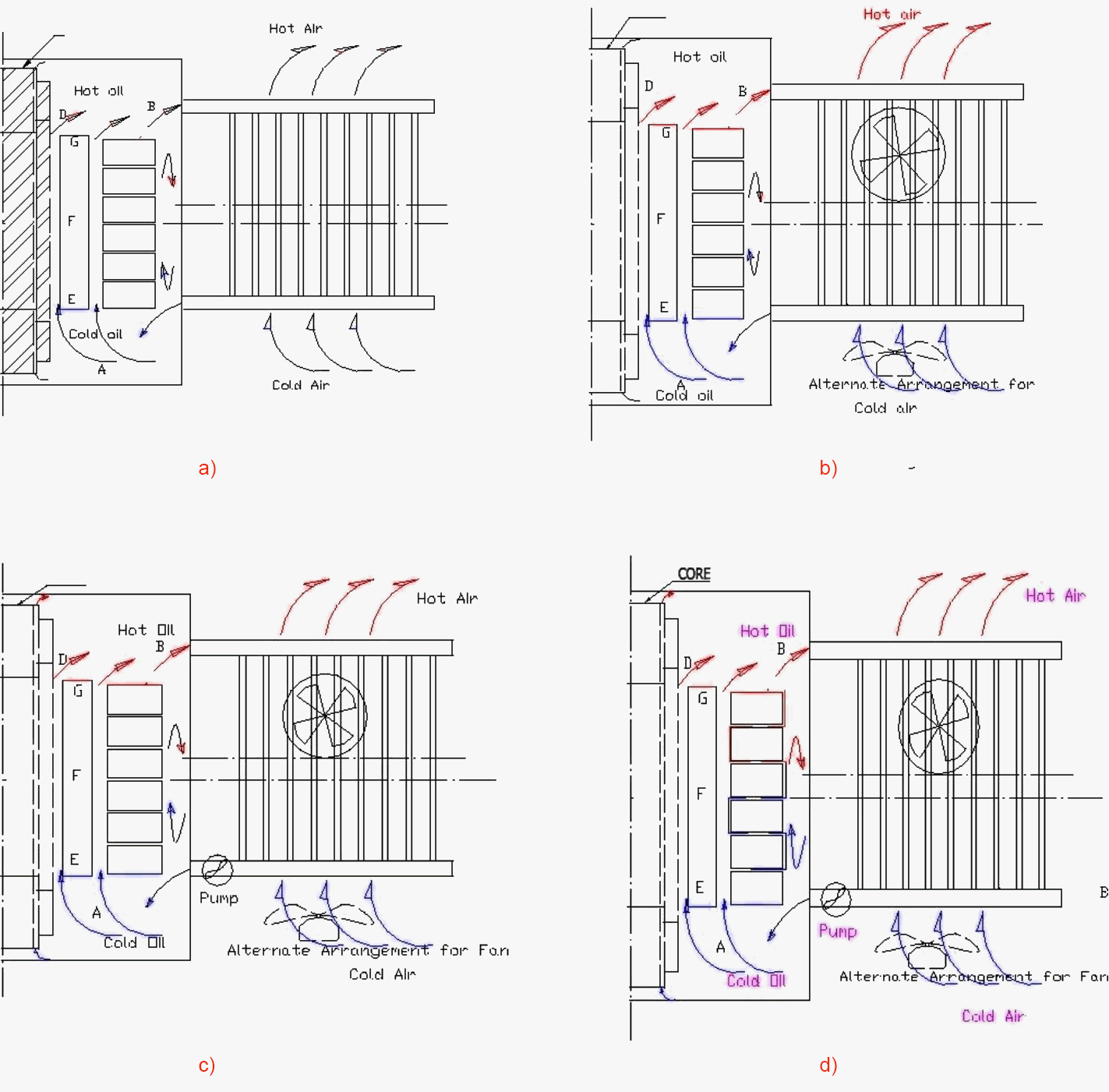
These types of cooling discussed below are usually indicated by a four-letter code. The common alternatives for oil-immersed and air-cooled transformers are:
Table 1 – The common alternatives for oil-immersed and air-cooled transformers
| ONAN (Oil-immersed, natural circulation) | Self-cooled by air – without oil pump or fan. |
| ONAF (Oil-immersed, natural circulation Forced Air Cooled) | Natural oil circulation- forced air cooling by fans. If fans are stopped transformer becomes ONAN type. |
| OFAF (Oil-immersed, Forced Oil, Forced Air Cooled) | Oil circulation through coolers forced by pumps – air flow by fans. |
| ODAF (Oil-immersed, Directed Forced Oil, Forced Air Cooled) | Oil flow by pumps, directed right in to the windings – air flow by fans mainly for large power transformers, above 100 MVA. |
Classes of transformers with respect to the method of cooling are as follows:
1. Oil-immersed, Self-cooled
Its simplest means of providing a sufficient cooling surface consists of immersing the transformer in oil contained in a closed tank. This method of cooling is usually found in transformers of sizes under 25 kVA. The use of this cooling system above 25 kVA usually becomes expensive as a large surface area is needed for the cooling surface.
In other words, the size of the tank will be too large. In order to solve this problem of the large requirement of surface area sinusoidal corrugation was used in earlier days. This enables to increase the several-fold surface area of the tank. The corrugation however doesn’t increase the heat dissipated rate in the same proportion to the increase in surface area.
Today, external metal tubes or channels are welded into the sides of a plain tank. Another method is to attach external radiators to a plain tank.
2. Oil-immersed, Water-cooled
This technology mainly practices in the American region. It replaces the above method for large units of the transformer when it becomes expensive to provide sufficient cooling area. This type of cooling is achieved by circulating water through spirally wound copper cooling coils assembled inside of a smooth tank. In order to prevent leakage of water into the oil, jointless coils are used in water-cooled transformers.
This method is quite efficient and cost-effective for large units but good maintenance is demanded when compared to the self-cooling method.
3. Oil-immersed, Forced-Oil-cooled
Oil-immersed, forced-oil-cooled transformers can be divided into two categories. First type in which the oil is pumped from the main tank through external oil to the water cooler. The second type is that in which the transformer oil is pumped through external oil to air cooler. In both of these cases, the oil may be directed or undirected.
See Figure 1 (c) and (d) over the windings in the transformer.
Reduction of size and weight of transformers are very important aspects in reducing investment cost and making it easier to transport from manufacture to customer site.
In forced oil cooling there is a limit to the rate at which the oil can be circulated, normally determined by diminishing reduction in temperature achieved as oil velocity increases. For extremely high oil flow velocities it’s possible to get static charging of the insulation and can lead to electric discharge and insulation failure.
Even if the oil is directed into the windings, some oil from the coolers will be allowed to pass directly into the tank to cool other parts like the core.
4. Oil-immersed, Forced-Air-cooled
This cooling method involves the use of high-velocity fans and pumps for cooling purposes. Forced air cooling increases the rating of the transformer up to 1.67 times that of a self-cooling transformer. Transformers with this cooling system can also be classified as having directed or non-directed flow into the windings.
Ratings of these transformers vary according to the number of fans in operation. The disadvantage of this type of cooling is that in the event of an auxiliary power failure, the transformer has no cooling capacity.
| Title: | A study of life-time management of generator step up power transformers – Chaitanya Upadhyay at E. ON’s Öresundsverket, Malmö |
| Format: | |
| Size: | 3.4 MB |
| Pages: | 74 |
| Download: | Right here | Video Courses | Membership | Download Updates |

