
IEC 61850
IEC 61850 is a relatively new international standard, which has been developed to define the communication infrastructure within the substation for the first version, and has been extended to support the protection and automation for the energy system within the second version.
The IEC 61850 standards have been expected to provide and ensure seamless communication as well as integration between IEDs from various manufacturers into a hierarchical level.
Substations Topologies
Energy systems have to be adapted according to needs. It has become necessary to transmit power for longer distances at higher voltages. Direct high voltage from a power plant cannot be used in homes or by businesses.
In such systems, various types of substations are implemented to adapt the distributed voltages.
Typically, transmission and distribution comprise the two types of substation. A transmission substation is usually supplied with a transmission-level feeder (100 kV and higher) which can connect two or more transmission lines that allow a single source of electrical power to be split into more outputs.
In the simple case, all transmission lines are of the same voltages. In another case, it may have a transformer to step up or step down voltages based upon needs.
The size of a transmission substation ranges from small (which may consist of a bus plus some circuit breakers) or large (consisting of multiple voltage bus levels, many circuit breakers and an enormous amount of monitoring protection and numerous control devices).
In this case, it may require a redundant communication link among the transmission substation devices, as well as between transmission substations and a control centre, to increase reliability. Figure 1 above illustrates the two types of transmission substations.
The ranges of the distribution substation voltages are between 3.4 kV- 33 kV depending on the size and coverage area served by the local utility.
Figure 2 illustrates two types of the distribution substations (IEC 61850-1)
Substation Monitoring and Control
Monitoring and control are the key features of an SAS allowing electrical utilities to coordinate any disturbance devices installed in the substation remotely.
Different types of devices are utilized within the SAS. These devices are integrated into a functional group based on their communication scheme for the purpose of monitoring and control. SASs seen rapid evolution in the last two decades.
Secondly, the vast amount of data and information provided by IEDs, which encourages researchers towards significant developments in communications systems based on the agreed and accepted usage of communications standards and protocols.
This allows for the use of equipment from the various manufacturers.
Thirdly, the merging of the objective of a sharing data beetween various devices inside SASs as well as outside them to limit cascade phenomenon based energy system failure.
Different types of the monitoring and control schemes have been implemented within SASs. However, they are outside the scope of this study.
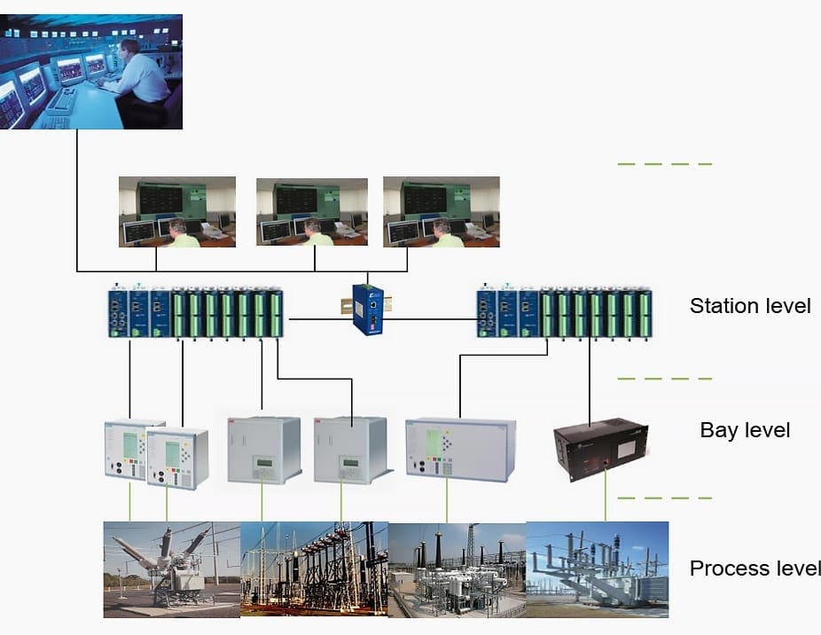
Figure 3 illustrates the conventional substation architecture where the centralizing scheme simplifies an SAS based upon the fact that all the interfaces are centered around the SCADA RTU. According to this classification, substation architectures can be divided into three hierarchical levels.
A substation’s primary equipment, such as circuit breakers, power transformers, switchgears, etc., and their link elements, such as instrument CTs, VT transformers, circuit breakers, etc., represent the level zero process level.
| Title: | On Reliability and Performance Analyses of IEC 61850 for Digital SAS – Mike Mekkanen at University of Vaasa Faculty of Technology; Department of Computer Science, Vaasa, Finland |
| Format: | |
| Size: | 28.30 MB |
| Pages: | 202 |
| Download: | Here 🔗 (Get Premium Membership) | Video Courses | Download Updates |
Suggested Course – Learn to Read and Analyze CCB Schematics & Control Wiring Diagrams
Learn to Read and Analyze Circuit Breaker Schematics and Control Wiring Diagrams

The title of the article and its contain is not matching. It should describe about what is IEC 61850 Comm. System? How to implement in SAS system? What benefit? What drawback? etc.
Interested
Neumerical Relay setting
I have read that electrical potential lines never crosses each other on equipotential surfaces.
Few years ago , I have observed one incident at hydro power generating station where Iam working . There was an earth fault on 400 KV system and at sametime 22KV feeder also got trip . Later on Checking relays of
400KV feeder was earth fault was confirmed . But at 22KV feeder relay there was also earth fault in relay and also later it got charged . Earth mat for 400KV and 22KV system is common .
Now question is can 400KV and 22 KV Electric Potential lines got crossed near to charge surface which causes tripping of 22KV when 400KV system tripped ?
directional fault current
Excellent informtaion, we are improving our knowledge by learning on this Electrical Portal..
Thanks for the excellent information!
Just a request IEC 61850 is a set of standards for communication as well as how to define the data object in the network. In the introduction if some details regarding this topic can be highlighted and also introduction to all the applicable standards will be helpful.
Your giving a wonderful information