Substation Installation up to 22kV
This guide provides various schematics and construction drawings for the installation of distribution substation plants operating at voltage levels up to 22kV. It aims to dictate consistent engineering practices, streamline procurement, and ensure maximum safety across the electrical grid.
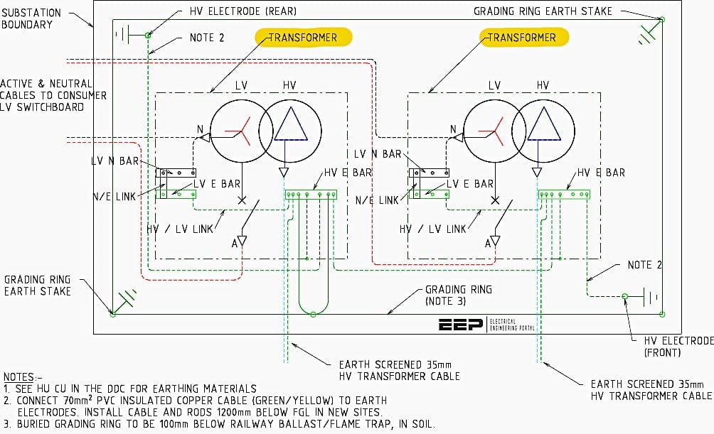
The manual outlines the standard plant arrangements for substations utilizing Tyree and ETEL transformers. By adhering to these standardized engineering drawings, POwer Utility guarantees that “standard substation equipment” can be seamlessly procured.
This standardisation drastically reduces overarching infrastructure costs and facilitates rapid, like-for-like equipment replacement during future maintenance or unexpected failures.
Standardized Drawing Sets: The Six-Sheet Blueprint
To ensure absolute clarity across all project phases, from estimation to physical installation, the manual categorizes standard drawings into two primary domains: Non-Fire Rated (outdoor) and Fire Rated (indoor) substations.
Regardless of the classification, each standard installation typically requires a comprehensive six-sheet drawing set:
Sheet 1 – Plant Single Line Diagram
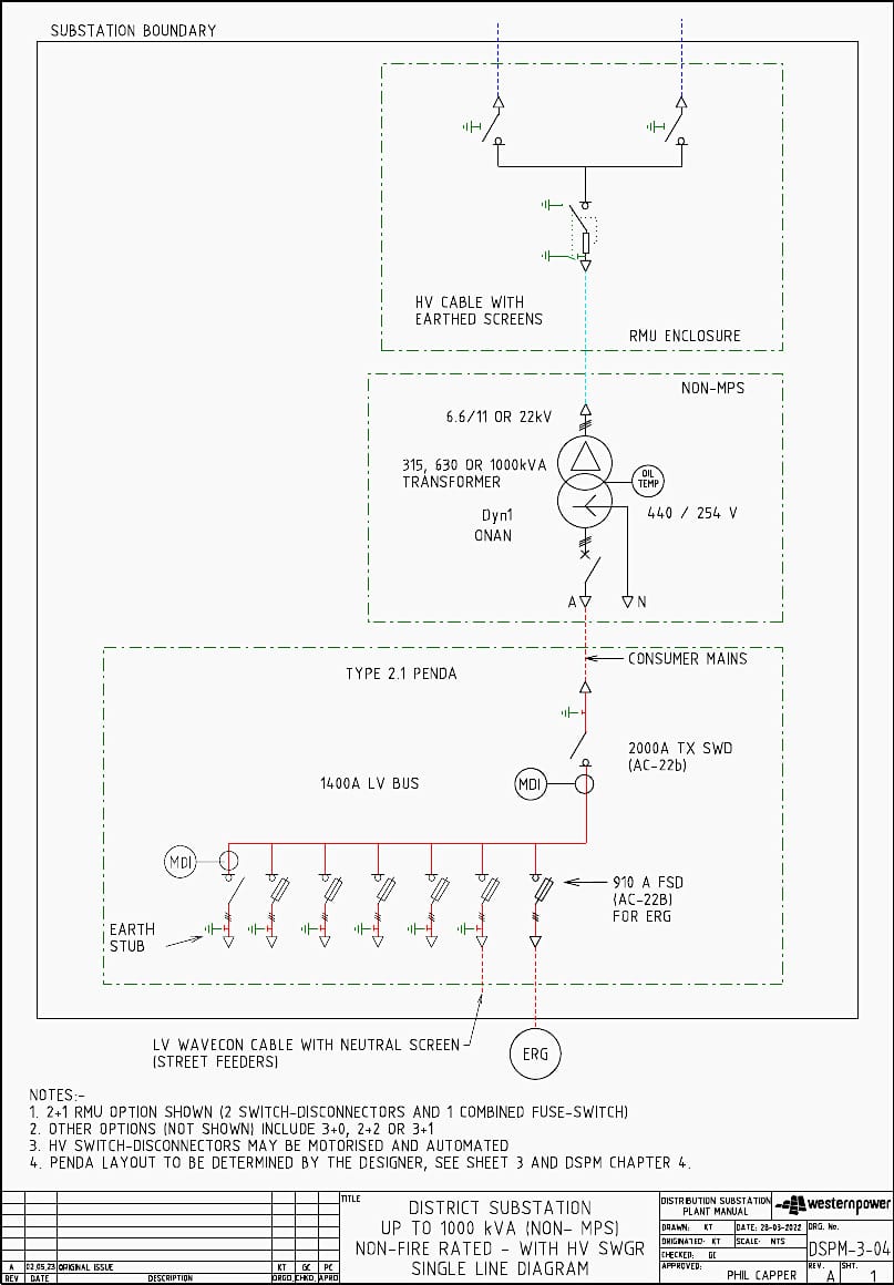
This initial schematic provides a diagrammatic representation of the electrical circuit. It maps out crucial electrical data, including the location of isolation switches, operational earthing points, voltage levels, electrical protection parameters, and the transformer vector group (such as Dyn1).
Figure 1 – SLD for a distribution substation up to 1000kVA
Sheet 2 – Land or Substation Building Requirements
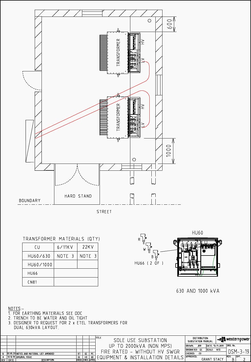
For non-fire rated outdoor sites, this sheet illustrates the minimum land footprint and cable ducting necessities. It empowers designers to factor in additional land for grading rings, earth retaining systems, personnel access, and oil containment bunds.
Conversely, for fire-rated indoor substations, this sheet dictates the architectural requirements of the fire-rated enclosure, detailing cable trenches, door placements, and wall-mounted air vents without dictating exact civil design details.
Sheet 3 – Plant, Equipment, and Substation Layout
Functioning as an assembly guide, this layout assists designers in generating accurate cost estimates and work orders. It explicitly marks the physical footprint of the transformers, ring main units (RMU), low voltage (LV) switchgear, and interconnecting power cables.
A strict ±50mm construction tolerance is applied to ensure components align perfectly with standard concrete culverts and enclosures.
Figure 2 – Distribution plant, Equipment, and Substation Layout
Sheet 4 – Clearances
Safety is very important, and Sheet 4 provides a visual representation of all required physical clearances.
This includes operational distances required for personnel to safely manipulate equipment, general access and egress routes, step-and-touch voltage earthing boundaries, transformer noise impact zones, and vital fire risk zones (dictating the distance from combustible surfaces).
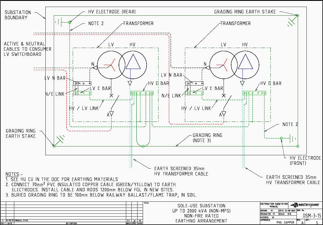
Sheet 5 – Plant Earthing Single Line Diagram
Effective earthing mitigates fatal electrical faults. This sheet outlines the combined High Voltage and Low Voltage earthing systems. It details the required number of earth electrodes, High Voltage Earth (HVE) bars, Low Voltage Earth (LVE) bars, neutral earthing links, and buried grading rings.
Figure 2 – Distribution substation layout and connections (up to 2000kVA)
Sheet 6 – Permissible Screening Arrangements or Fixing Details
For outdoor substations, aesthetic or protective screening is often required by landowners. This sheet demonstrates where non-combustible screening can be legally placed without encroaching on the substation’s operational footprint or fire risk zones.
For fire-rated indoor sites, this sheet instead provides precise Switchgear Fixing Details, showing how to position RMUs over trenches and install cantilever support brackets securely.
Substation Categories & Voltage Configurations
The manual is highly exhaustive, scaling its standardised six-sheet approach across a multitude of network requirements. It categorises designs into District Substations and Sole Use Substations, providing variants for both non-fire rated and fire-rated environments.
These designs comfortably accommodate varied network voltages, including 6.6kV, 11kV, 12.7kV (single phase), and 22kV systems.
Guide Summary
In summary, this guide is a vital technical instrument for Power Utilities. By rigidly defining the electrical, spatial, civil, and safety requirements of distribution substations through standard six-sheet drawing sets, the manual ensures that the electrical network remains safe, cost-effective, and highly maintainable for years to come.
| Title: | Installation Guide for Distribution Substation Plants – Western Power |
| Format: | |
| Size: | 18.2 MB |
| Pages: | 140 |
| Download: | Here 🔗 (Get Premium Membership) | Video Courses | Download Updates |
Good Reading – Sheet-By-Sheet Analysis of 10kV Motor Control Centre (MCC) Technical Drawings in EPLAN
Sheet-By-Sheet Analysis of 10kV Motor Control Centre (MCC) Technical Drawings in EPLAN