Maintenance optimization for substations
When make maintenance related decisions for entire system other than single equipment, it is desired to know the expected system reliability improvement and cost. Therefore, this paper will focus on developing system level reliability and cost models with respect to equipment maintenance. Also, the dissertation presents several scenarios about how to utilize the developed models to optimize maintenance decision.
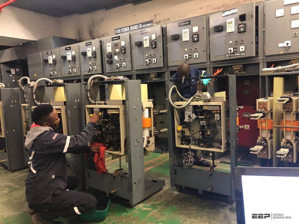
Power substations
Electricity is generated and delivered to end customers through generation, transmission and distribution systems. Generation systems produce enough power to meet customer demand. Transmission systems transport bulk power without overheating or jeopardizing system capacity/stability over long distances. At the end, distribution systems distribute power and deliver electricity to end customer’s service.
In terms of reliability, generation, transmission and distribution systems are referred to as functional zones. A simple drawing of an overall power system in different zones is presented in Figure 1.
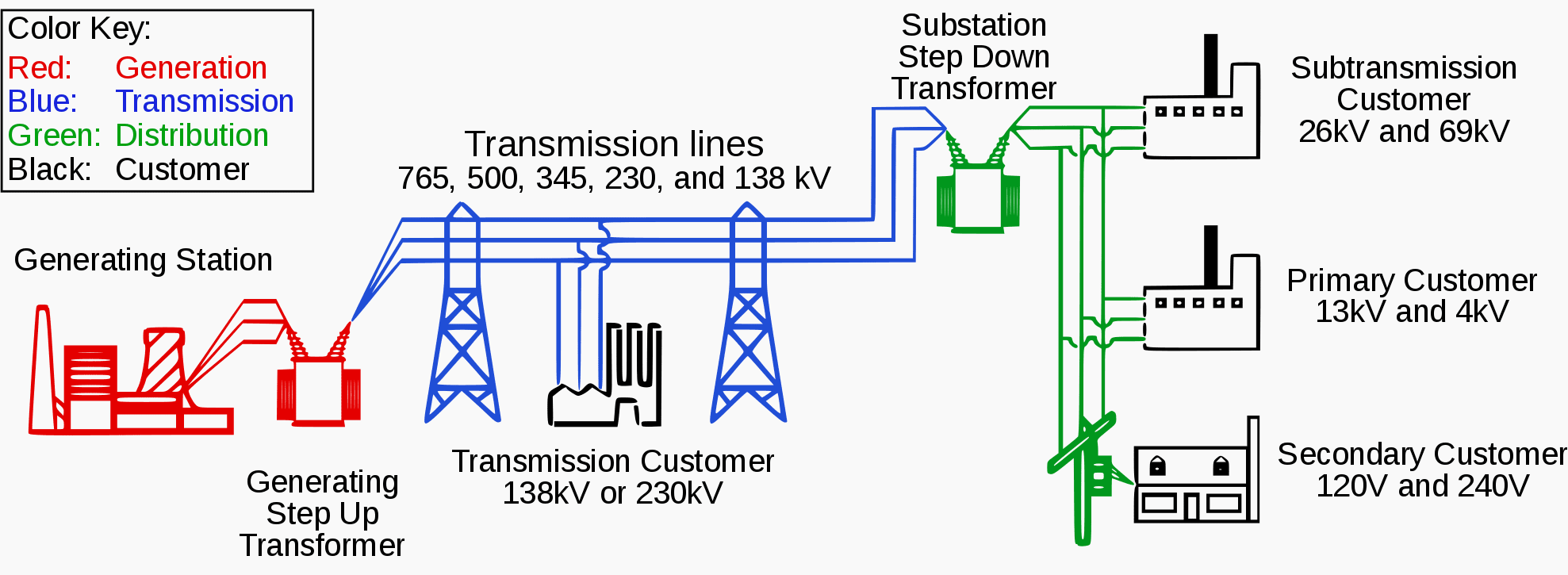
In Figure 1, substations play different roles in different systems: generation substations connect generation plants to transmission lines through step-up transformers, that increase voltage to transmission levels. Transmission substations are transmission switch stations with transformers that step-down voltage to sub-transmission levels.
There are also transmission switch stations which serve as nodes that allow transmission lines to be reconfigured; distribution substations are nodes for terminating and reconfiguring sub-transmission lines, with transformers that step-down voltage to primary distribution levels.
The dissertation focuses on the distribution substations, since most customer failures are related with distribution systems. However, the proposed methods are general, and can also be applied to substations in generation and transmission systems.
Substation Structure
There are various types of substations depending on functionalities. A popular and simple substation diagram is presented in Figure 2.
In Figure 2, the source of delivering power to the substation is a single subtransmission line. Power is delivered across disconnect switch, through circuit breaker,and enters power transformer.

Several current transformers (CT) and voltage transformers (VT) are connected in parallel, which are mainly for measurement purposes. The circuit breaker protects the transformer that steps voltage down to distribution level.
This single-line substation structure may cause reliability concerns, due to its simple configuration: any major component failure will results in all feeders to be deenergized.
Consequently, many distribution substations are designed with redundancy, to allow portions of feeders remain energized if any major component fails or not available due to maintenance.
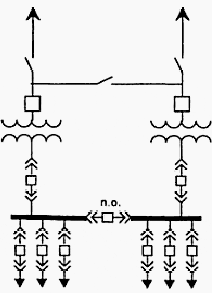
Figure 3 is an “H-station” or “transmission loop-through” design substation. This substation is able to supply both secondary buses, after the loss of either transmission lines or transformer. This structure also has disadvantages that faults will generally cause one of secondary buses to be de-energized, until switching is performed.
Figure 4 is a substation that further increases substation reliability, by having an additional transmission line, an energized spare power transformer, primary ring-bus protection, motor-operated switches, and a secondary transfer bus.
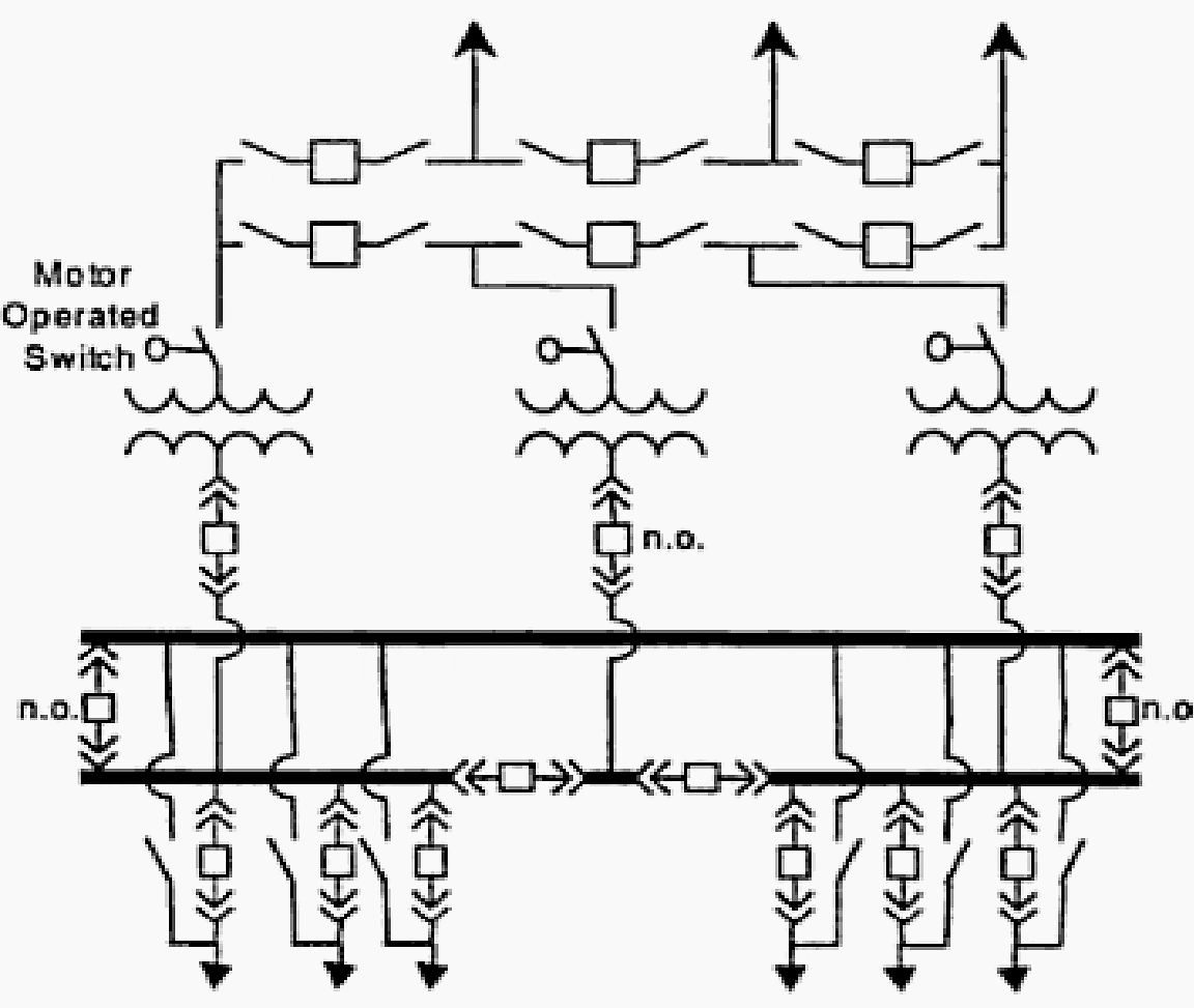
The comparison of Figure 2 , Figure 3 versus Figure 4 indicates that reliability is improved when the number of buses or sections of buses increases. In fact, bus configurations play an important role for substation reliability, operational flexibility and economic costs.
In practice, because of the high reliability and relatively low cost, it is common to initially build a substation as a ring bus, and convert it to breaker and a half when required.
| Title: | Impact of maintenance toward substation equipment and economic cost – Haifeng Ge at University of Nebraska at Lincoln |
| Format: | |
| Size: | 2.2 MB |
| Pages: | 212 |
| Download: | Right here | Video Courses | Membership | Download Updates |


let me ask u about Pramac Generators its generate about 400Vac but my question is if u know about the generator give information . and if its possible give about power factor correction electrical drawing.