
Electrical connections for NERs
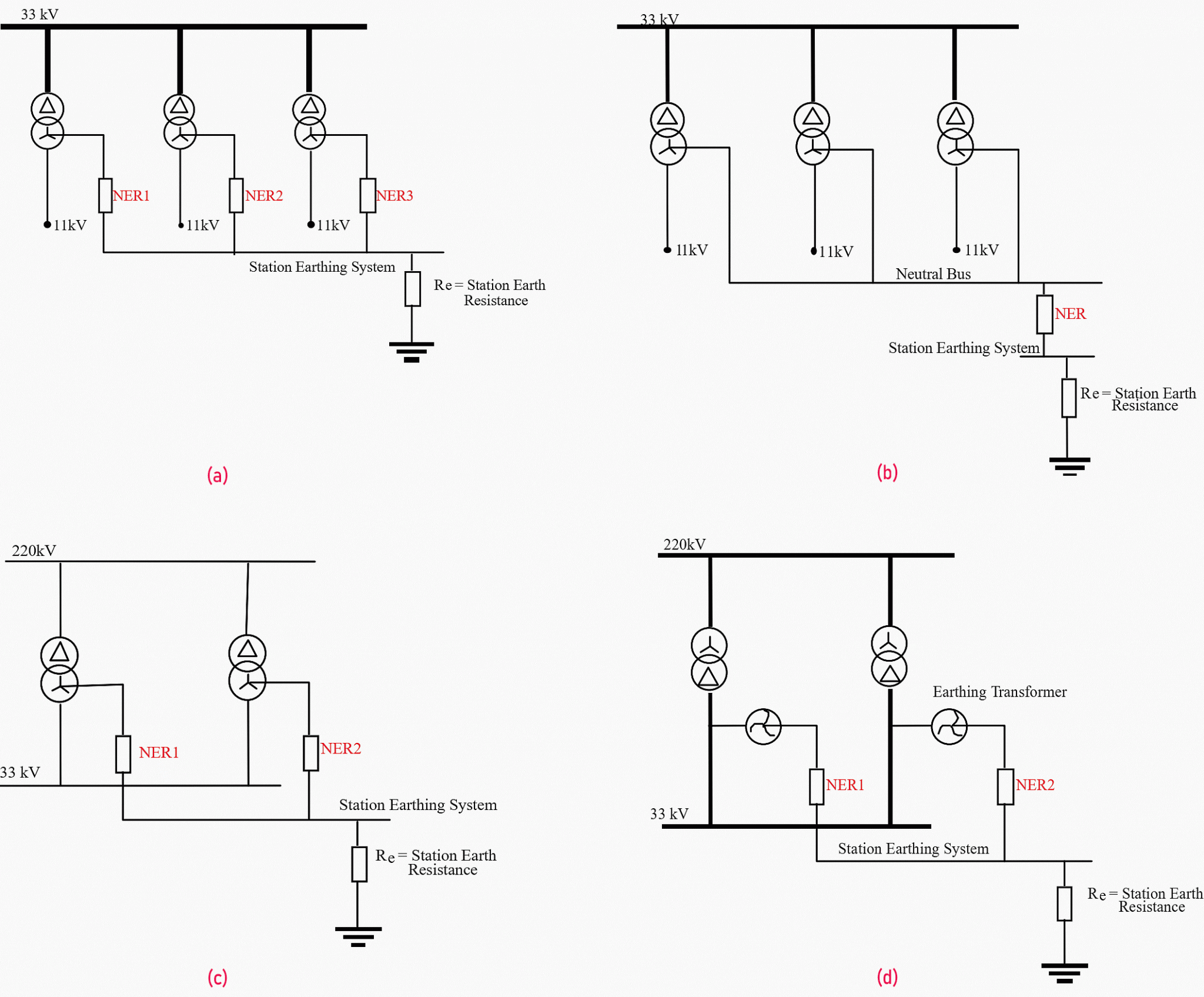
There are two main approaches generally adopted when applying impedance earthing techniques: one NER per transformer unit and one NER per substation serving one or more transformer unit(s). For one NER per transformer unit the maximum 11 kV earth fault current will depend on the number of transformers operated in parallel (since the associated NER’s are also effectively connected in parallel).
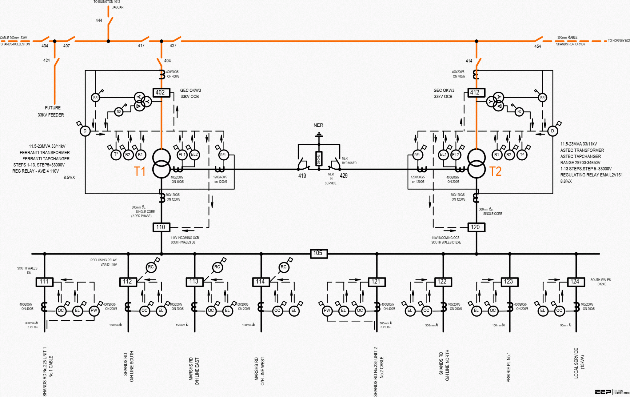
Refer to Figure 1 (a), (b), (c), (d).
Where one NER serves all the transformers at the substation, the maximum 11 kV earth fault current is usually independent of the number of transformers and is determined largely by the NER value.
In a 33/11 kV substation with one NER connected to a number of transformers it can be shown that for values of NER greater than approximately 3-4 ohms the available earth fault current converges to a constant value for an earth fault close in to the substation independent of the number of transformers in parallel service.
The following table outlines the merits/demerits of each type of NER connection.
| One NER per transformer unit | One NER per substation serving one or more transformer unit(s) |
| Easier maintenance in that each transformer/resistor can be withdrawn from service as a unit if required | Requires consideration of switching and isolation switching and isolation arrangements for allowing safe working on units still in service. |
| More NERs per substation, hence higher costs. | Only one NER per substation, hence lowest cost. Also more suitable where restricted space is a problem. |
| Higher earth fault current levels. Earth fault current varies depending on the number of transformers in parallel. | Lower earth fault current levels. Earth Fault Current not dependent on the number of transformers in service. Essentially fixed level of earth fault current. |
The choice between the two cases is mainly determined by the choice of NER. Early applications of neutral resistance involved liquid resistors which require regular routine maintenance. Where these units are associated with non-dual rated transformers, one resistor per transformer has generally been used.
Associated with NER installation is the requirement for bypassing and isolating, arising from testing and maintenance considerations.
The preferred solution is to interlock the NER isolation and bypass switches in such a way as to make it impossible to accidentally disconnect the neutral point from earth.
Although NER’s will operate for most of their life at or near earth potential, they have to be treated as high voltage devices in terms of insulation rating, testing and maintenance. The connection arrangement chosen must allow for routine servicing or repair of the NER at some future date after commissioning.
Installation of NER(s)
Two distinct situations arise depending on whether an NER is being retrofitted to an existing transformer or a new installation is being constructed with impedance earthing provided in the design.
Retrofit of an NER
In the retrofitting case, space limitations may be significant. During a phase to earth fault, the NER and associated connection equipment is subject to voltages up to at least the normal phase to neutral system voltage (e.g. 6350 volts for an 11 kV system).
New Installations incorporating NER’s
In a brand new installation space may still be limited and this may influence the type of NER employed. If liquid resistors are to be used, dependant on climatic conditions, it may be desirable to provide a sheltered environment to reduce standing heating losses.
Other types of resistors may benefit from improved air flow to attain a suitable heat dissipation rating.
| Title: | Handbook for application of neutral earthing resistors or reactors (NERs) at the substation – The New Zealand Committee for the Co-ordination of Power and Telecommunication Systems Inc. |
| Format: | |
| Size: | 1.6 MB |
| Pages: | 98 |
| Download: | Here 🔗 (Get Premium Membership) | Video Courses | Download Updates |

When there is some problem in the 11kv/230v transformer like a bird shorts two wires some of equipment gets repaired. A fan or light in switched off condition got into fire and sound
what the correct value of NER for substation 33/11 kv with daul transformers each 16 MVA
and how calculate the R value and I fault value.
The technically what is real difference between earthing and Ground
The earthing is done to protect the operator from the fault current and grounding is done to protect the utility system to protect from fault current. The earthing is done on the LV side and grounding is done on the HV side.
Fluctuation normally a problem from the distribution utility because the incoming voltage is not stable. I suggest to install a automatic voltage regulator in primary line side after the service drop
I have a problem in the factory there is a fluctuation in the main electricity source of 22 kVA, and this leads to the stoppage of production lines and consequently an increase in the amount of waste,
This is repeated permanently
What are the technical solutions that can be taken to avoid this problem?
Check your power quality ( Harmonics and PF). You may need to install PFC or Harmonic Filters. Check all the harmonics.