Search

Premium Membership ♕

Limited Time Offer: Save 15% on PRO Plan with discount code: LRN15 and study specialized LV/MV/HV technical articles and studies.

Home / Download Center / Electrical Engineering Books and Technical Guides / Power substation guides / Partial Discharge Analysis in HVDC GIS (Gas Insulated Substations)

Gas Insulated Substations

Gas Insulated Substations (GIS) respond to the expansion of the grid as well as the scarcity of available locations to build substations. In fact, GIS are multi-equipment systems in which the insulating medium is mainly SF6 whose insulating properties permits to drastically reduce the dimensions of the substation in comparison to a traditional open-air one.

Partial Discharge Analysis in HVDC GIS (Gas Insulated Substations)

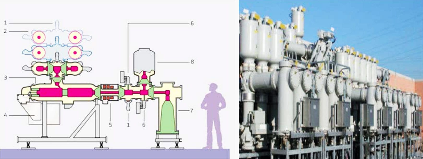
The GIS have a sealed metal-enclosure that keeps the gas under pressure and avoids leakage of SF6, a strong greenhouse gas. In Figure 1 is shown a representation of a section of a GIS.

The systems is composed both of primary equipment (e.g circuit breaker) and secondary equipment (e.g. current transformer) and it can be installed in open-air or inside a building as it is permitted by the compact dimensions.

Although GIS have low-maintenance requirement, the equipment reliability may be hindered by undesired metal particle which subjected to an intense electric field can create Partial Discharges (PDs). PDs are responsible for many failure mechanisms of GIS.

To mention only few of them, a free moving particle approaching the conductor may trigger a flashover or if it lays on a spacer can lead to the carbonization of the latter.

PDs are also responsible for generation of corrosive by-products of SF6 which are harmful for both spacers and conductive parts.

Representation of a Gas Insulated System
Figure 1 – Representation of a Gas Insulated System: 1- Earthing Switch; 2 – Busbar disconnector; 3 – Circuit breaker; 4 – Spring operating mechanism; 5 – Current transformer; 6 – Feeder disconnector; 7 – Cable termination enclosure; 8 – Voltage transformer. The images refers to a B105 Alstom GIS.

The principal PD sources responsible for failures of GIS are:

  1. Fixed protrusion;
  2. Free moving particle;
  3. Floating electrode;
  4. Particle fixed on the spacer surface;
  5. Void in insulators.

A service experience study reported by C. Nuemann in his work “PD measurement on GIS of different design by non-conventional UHF sensors,” Cigre’ in Paris, 2000 on 123 kV and 420 kV GIS, shows the main causes of dielectric failure.

Pie chart of the main causes of failures in 123 kV GIS and 420 kV GIS according with a study of some German utilities
Figure 2 – Pie chart of the main causes of failures in 123 kV GIS and 420 kV GIS according with a study of some German utilities

From Figure 2 appears that at least 50% of the causes of failures, both for 123 kV and 420 kV GIS, are related to defects that are detectable by PD diagnostic and in particular related to particle on surface, on enclosure and on HV conductor.

Furthermore, from 60% to 70% of the failures could have been detected by monitoring systems with a sufficient sensitivity.

These figures mark the relevant role played by PD monitoring as a potential tool for failure prevention and maintenance scheduling.

Title:Partial Discharge Analysis in HVDC GIS (Gas Insulated Substations) – Thesis by Mr. Roland Piccin at Delft University of Technology
Format:PDF
Size:8.20 MB
Pages:145
Download:Right here | Video Courses | Membership | Download Updates
Partial Discharge Analysis in HVDC GIS (Gas Insulated Substations)

Premium Membership

Get access to premium HV/MV/LV technical articles, advanced electrical engineering guides, papers, and much more! It will help you to shape up your technical skills in your everyday life as an electrical engineer.
50% Discount 💥 - Save 50% on all 90+ video courses with Enterprise Membership plan.

More Information

Leave a Comment

Tell us what you're thinking. We care about your opinion! Please keep in mind that comments are moderated and rel="nofollow" is in use. So, please do not use a spammy keyword or a domain as your name, or it will be deleted. Let's have a professional and meaningful conversation instead. Thanks for dropping by!

  +  one  =  nine

Learn How to Design Power Systems

Learn to design LV/MV/HV power systems through professional video courses. Lifetime access. Enjoy learning!

Subscribe to Weekly Newsletter

Subscribe to our Weekly Digest newsletter and receive free updates on new technical articles, video courses and guides (PDF).
EEP Academy Courses - A hand crafted cutting-edge electrical engineering knowledge