
Transformer Testing & Commissioning
The reliability of a nation’s electrical grid hinges on the integrity of its core components, and few assets are as critical as power transformers. In the Kingdom of Saudi Arabia, the rapid expansion of industrial, commercial, and residential infrastructure demands a highly robust power distribution and transmission network. To guarantee this reliability, strict adherence to standardized Testing and Commissioning (T&C) procedures is mandatory.
This guide outlines the standard T&C protocols for power transformers, explicitly aligned with the rigorous requirements of the Saudi Electricity Company (SEC), the National Grid SA (NG), and Elsewedy Electric standards.
By following these structured guidelines, engineering teams can ensure seamless energization and long-term operational success.
The Core Purpose of Standardization
The primary purpose of this standardized procedure is to establish a unified, infallible approach to the Testing & Commissioning of power transformers installed across the Kingdom. A standardized approach eliminates guesswork, mitigates risks, and ensures that every transformer, regardless of its location or application, meets the exact same high-quality criteria.
Specifically, these procedures are designed to ensure:
1. Safe Inspection, Testing, and Energization: Prioritizing human life and asset protection above all else.
2. Absolute Compliance: Meeting the stringent specifications laid out by SEC and National Grid SA.
3. Comprehensive Verification: Confirming the electrical, mechanical, and operational integrity of the transformer before it ever sees live grid voltage.
4. Project-Wide Standardization: Creating a unified testing language and methodology across all Elsewedy Electric projects, from urban substations to remote industrial complexes.
Scope of Application
This T&C framework is highly versatile, designed to apply to all power transformer cooling types, including:
- ONAN (Oil Natural Air Natural)
- ONAF (Oil Natural Air Forced)
- OFAF (Oil Forced Air Forced)
- ODWF (Oil Directed Water Forced)
It encompasses every on-site test required from the moment the transformer is fully assembled until the final green light is given for pre-energization.
Key Personnel and Responsibilities
A successful commissioning phase relies on a synchronized team of experts, each with clearly defined roles to ensure quality and safety.
Testing & Commissioning (T&C) Engineer
The T&C Engineer is the hands-on technical expert. Their responsibilities include executing all tests correctly according to the approved sequence, strictly applying all safety rules, and validating the on-site results by comparing them directly with the Factory Acceptance Test (FAT) baseline.
Finally, they are responsible for compiling and issuing the formal T&C reports.
T&C Section Head
Operating at a supervisory level, the Section Head reviews all site-specific procedures to ensure overarching standards are met. They serve as the final technical authority, approving all T&C documentation and resolving any complex technical discrepancies that arise in the field.
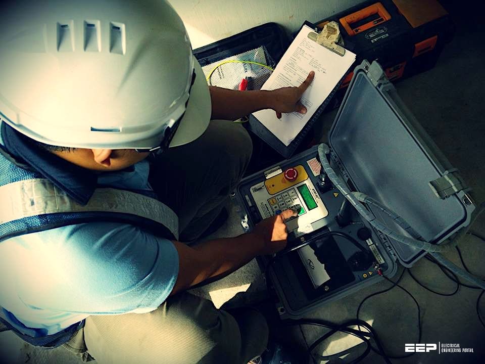
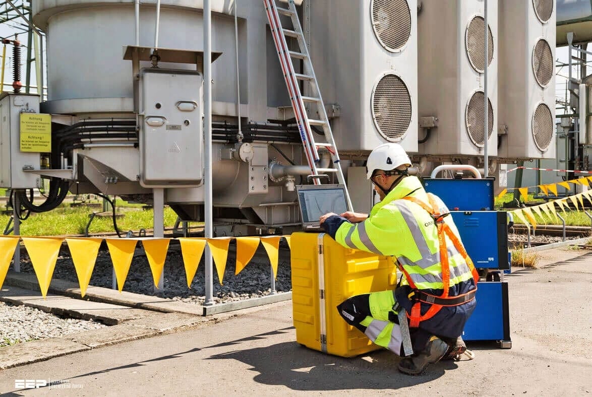
Figure 1 – Testing and commissioning power transformer
QA/QC Engineer
Quality Assurance and Quality Control are vital. The QA/QC Engineer acts as an independent observer, witnessing the critical tests to guarantee transparency. They also audit the documentation to ensure all forms, checklists, and test records are entirely accurate and comprehensively filled out.
Client / Consultant
Representatives from the client (such as SEC/NG) or their appointed consultants attend designated “witness points.” Their final approval is the ultimate gateway to declaring the transformer ready for energization.
Safety Officer
The Safety Officer holds the authority to halt any activity. They ensure that the Permit to Work (PTW) and Lockout/Tagout (LOTO) procedures are impeccably applied, effectively preventing any unsafe actions during the high-risk testing phase.
Required Tools & Instruments
High-precision testing requires high-precision instrumentation. The standard testing toolkit must include calibrated, industry-approved devices:
- SFRA Analyzer: To detect mechanical deformations in the core and windings.
- TTR Device: For precise Transformer Turns Ratio verification.
- Winding Resistance Tester: To measure DC resistance and verify contact integrity.
- Tan Delta Set: To measure the capacitance and dissipation factor of insulation.
- Megger Tester (5 kV): To measure Insulation Resistance (IR) and Polarization Index (PI).
- AC Current Injection Set: For simulating operational loads and verifying protection circuits.
- OLTC Analyzer: To assess the timing and transition of the On-Load Tap Changer.
- CT Analyzer: To verify the performance of internal Current Transformers.
- Multimeter / Clamp Meter: For general electrical measurements and troubleshooting.
- Torque Wrench: To ensure all mechanical and electrical connections are tightened to specification.
- Thermal Camera: For detecting hotspots during initial loading phases.
- Oil Sampling Tools: To extract dielectric fluid for precise chemical and electrical breakdown analysis.
Strict Safety Requirements (SEC/NG Standards)
Safety in an SEC/NG substation environment is non-negotiable. Before a single test lead is connected, strict safety perimeters must be established.
A valid Permit to Work (PTW) must be issued and clearly displayed. LOTO (Lockout/Tagout) protocols must be applied on all incoming and outgoing connections to ensure the transformer cannot be accidentally energized.
Personnel must wear mandatory Arc-flash Personal Protective Equipment (PPE). Under no circumstances is testing permitted under live circuits. Furthermore, any physical anomalies, such as gas or oil leaks, must be completely resolved before any electrical testing commences.
The Standard Test Sequence
The order of testing is deliberate, designed to build a progressive profile of the transformer’s health without risking damage.
1. Visual & Mechanical Inspection
Before applying voltage, a thorough physical inspection confirms that the transformer was not damaged during transit, that all accessories are correctly installed, and that oil levels are adequate.
2. SFRA (Sweep Frequency Response Analysis)
Performed first, SFRA acts as a mechanical “fingerprint.” It checks if the internal core or windings shifted or deformed during heavy transportation.
3. TTR (Transformer Turns Ratio) – All Taps
This confirms that the fundamental voltage transformation ratio matches the nameplate design across every single tap position.
4. DC Winding Resistance – All Taps
Injecting DC current allows engineers to measure the resistance of the windings. This highlights any broken conductor strands, loose internal connections, or high-resistance contacts within the tap changer.
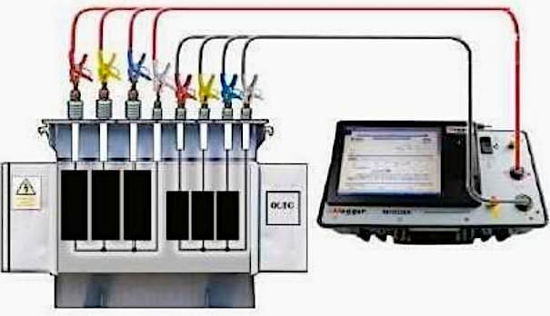
Figure 2 – Transformer Winding Resistance Test Connection
5. Tan Delta – Windings & Bushings
This diagnostic test assesses the dielectric health of the insulation system (both paper and oil) by measuring the dissipation factor. High values indicate moisture or degradation.
6. Insulation Resistance (IR) and Polarization Index (PI)
Using a 5 kV Megger, this test checks the fundamental resistance between the windings and ground. The PI provides a ratio that indicates the overall dryness and cleanliness of the insulation.
7. Magnetic Balance
A low-voltage test used to detect any major inter-turn short circuits or magnetic core imbalances.
8. Zero Sequence Test (if applicable)
Performed on specific winding configurations (like star-connected windings) to determine the zero-sequence impedance, crucial for accurate ground-fault protection settings.
9. AC Tests
- Short Circuit Impedance (Z%): Verifies the transformer’s impedance matches the FAT results, ensuring it will share load correctly in parallel operations and limit fault currents properly.
- No-Load Test: Measures the core losses (iron losses) and the magnetizing current required to energize the core.
10. Functional Tests
Once the core and windings pass, the auxiliary systems must be proven:
- OLTC Operation: Verifying smooth, accurate mechanical and electrical transitions of the tap changer.
- Fan / Cooling System: Ensuring pumps and fans activate correctly on command.
- WTI / OTI Simulation: Simulating temperature rises to verify that Winding Temperature Indicators and Oil Temperature Indicators respond accurately.
- Alarms & Protections: Tripping the Buchholz relay, pressure relief devices, and temperature sensors to guarantee they send the correct alarm and trip signals to the control room.
11. Final Pre-Energization Checks
The final step is a comprehensive review. The T&C engineer ensures all grounds are removed, valves are in the correct operational position, test leads are cleared, and the site is pristine.
Only upon the successful completion of this rigorous sequence is the power transformer deemed ready for safe energization into the power grid.
| Title: | A Guide to Power Transformer Testing and Commissioning Procedures |
| Format: | |
| Size: | 1.9 MB |
| Pages: | 60 |
| Download: | Here 🔗 (Get Premium Membership) | Video Courses | Download Updates |
Further Study – Guidelines to distribution transformers for industrial and commercial electrical supply
Guidelines to distribution transformers for industrial and commercial electrical supply
