
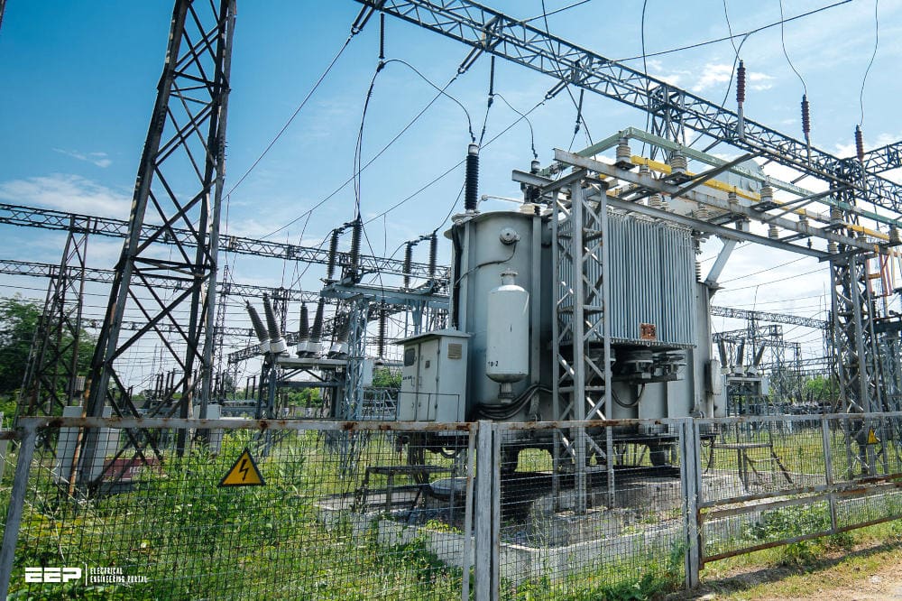
Earthing in an electric power system
It is pertinent to mention that Earthing plays an important role in proper operation of generation, transmission and distribution systems. The function of earthing in an electric power system is to maintain the potential of current carrying as well as non-current carrying parts of equipment, apparatus and appliances connected to the system, and to ensure safety of equipment and personnel and correct operation of protective devices during earth faults.
Earthing also provides safety during lightning strikes on equipment or structures and on occurrence of induced voltage and current on electric equipments of an electric system. Moreover, proper earthing system provides easy and shortest path to the low of earth fault current without adversely affecting the continuity of service.
The eficacy of an earthing system depends on various factors like resistivity of general mass of earth in and around the area where earth grid is buried and also that of surface layer of soil, duration and magnitude of fault current and grid current, shock duration, the maximum safe current that a human body can tolerate and the permissible values of dangerous voltages that shall arise due to the low of grid current.
Earthing of fence is another issue of importance.
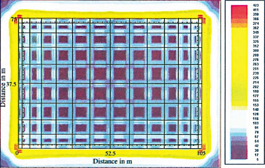
Figure 1 – Overall step voltage plot for non-uniformly spaced grid
Execution, Field Practices, Monitoring and Maintenance of Earthing Systems
Earthing system of a station should provide reliable performance during the life of the station. The earth electrode, being underground, can be the case of out of sight out of mind. It is of utmost importance that construction of earth electrode is carried out by strictly adhering to the design.
Once the earthing system is installed, it is important to carry out periodic inspections and testing and take remedial measures to maintain its performance.
In this book, various aspects related to construction and maintenance of earthing systems are brought out.
Execution of Earthing System
A station earthing system is typically composed of ive key components, namely
- The soil,
- Vertically installed bare metallic rods / pipes / plates and horizontally installed bare conductors in the soil,
- Overhead shield wires and lightning masts,
- Layer of high resistivity gravel on top of the soil, and
- Bare / insulated conductors which connect all metallic structures, enclosures of all equipment including metallic conduits and cable trays, etc. with underground, buried vertical rods / pipes / plates and/or horizontal conductors.
The effectiveness of the earthing system depends on the condition of the buried conductors and the integrity of the connections between earth conductors and between earth conductors and the structures.
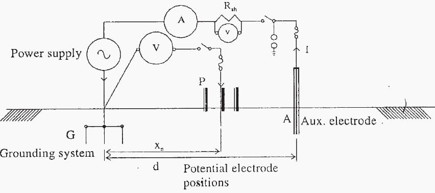
Figure 2 – Current Injection method using external source of power
Construction of Grid Earth Electrode
The construction of earthing system depends on a number of factors, such as size of grid electrode, its depth of burial, size of earth conductor, type of soil, availability of equipment, cost of labour, and any physical or safety restrictions due to the presence of nearby, existing structures or energized equipment.
Construction Sequence for Earthing System Installation
An earth grid is normally installed after the yard is graded, foundations are laid, and deeper underground pipes and conduits are installed and backilled. It may be prudent to wait until construction of plinths and other structures have been largely completed to avoid possible damage to earth conductors.
The required connections to equipment and structures are made after the horizontal earth conductors are placed in trenches.
The security fence may be installed before or after the earth grid installation. In cases where deeper underground pipes and conduits are not installed before earth grid installation, an attempt should be made to coordinate the trenching procedure in a logical manner.
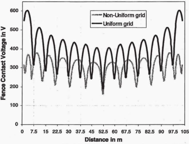
Figure 3 – Fence contact voltage for uniformly and non-uniformly spaced grid of conductors
General Practices for Construction of Grid Earth Electrode
Practice №1
The bare MS conductors forming grid electrode are generally laid at a depth of about 300 mm to 600 mm below ground level. The minimum depth is recommended for protection of conductors and connections against mechanical damage during subsequent excavation works.
Actual depth of horizontal grid conductors should be in accordance with design calculations to keep dangerous voltages and EPR within acceptable limits.
Practice №2
At large substations, it will be advantageous if earth conductors are laid on one side of excavations made for cable trenches, field drains, and other civil works.
Practice №3
The conductors should be surrounded by 150 mm of non-corrosive soil of ine texture, firmly rammed.
Practice №4
The connection between vertical rods and horizontal conductors can be made using various methods. However connections between horizontal grid conductors should be welded/brazed / exothermic type, as assumed for calculation of their area of cross-section to carry the maximum fault current during earth fault conditions in the system.
Practice №5
Where bare earth conductors cross over or are laid touching power or multi core cables, they should be insulated with PVC tape or sleeve to counteract possible puncturing of cable sheath arising from high voltage transients on earth conductors.
However metallic sheath / armour of cables are to be bonded with the earthing system in accordance with the recommendations given in the design and speciications for the earthing system of the stations.
Practice №6 – Speciic guidelines / recommendations for earthing of equipment / structures are given under section 8.3.
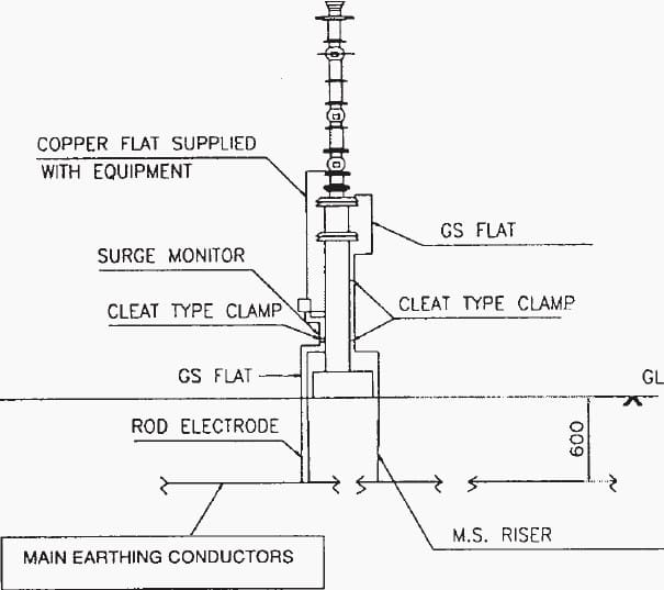
Figure 4 – An example of earthing arrangement of surge arrestor
Measurements And Field Quality Checks
Visual inspections, field tests and measurements should be carried out to ensure that the earthing system is installed in accordance with the applicable standard(s), design, technical speciications, and well accepted practices.
For conducting field tests and measurements, proper equipment and facilities are required.
Measurement of Substation Earth Resistance and Earth Impedance
Measurements shall be carried out after construction, where necessary, to verify adequacy of the earthing design. Measurements may include earthing system impedance / resistance, prospective touch and step voltages at relevant locations and transferred potential, if appropriate, as per procedures given in Chapter 10.
Although the measurements may pose some dificulties, if properly done, measured values are more exact than calculated values. When the soil is non-uniform and the earthing system is large and complex, measurements to check the theoretical calculations are advisable.
Records shall be kept of the initial measured earth resistance of substation and/or generating station earth electrodes and of tests carried out subsequently. Adequate safety and precautionary measures are to be taken during the test and measurements as discussed in Chapter 10.
All tests / measurements recommended under section 8.4 for periodic monitoring of earthing system / earth electrodes must be carried out after the completion of respective construction / erection works. Results of these and all other tests / measurements shall be documented to serve as reference for
- Acceptance of design and construction of earthing system, and
- Monitoring and maintenance of earthing system.
Good Reading – Electrical thumb rules for switching, isolating and earthing
Electrical thumb rules for switching, isolating and earthing
Field Quality Checks / Inspections
All physical checks / inspections that are recommended under this section and section 8.4 for monitoring and inspection of earthing system / electrodes are to be carried out after the completion of respective construction / erection works. Results of all physical checks / inspections shall be documented to serve as reference for:
- Acceptance of design and construction of earthing system, and
- Monitoring and maintenance of earthing system.
Field quality checks / inspection are to be carried out during the erection and construction activities to ensure that the following general and all other details are in accordance with design/ speciications of station earthing system and well accepted practices:
- Material, dimension and physical condition of horizontal conductors and vertical electrodes,
- Layout, spacing and depth of horizontal conductors of earth electrode,
- Dimensions, locations and depth of vertical electrodes including construction of their chambers / pits, application and compaction of backill around electrodes, watering arrangement and connections between vertical electrode and (a) main conductors of earth electrode and (b) earthing lead conductors from equipment /structures,
- All welded / brazed / exothermic connections between horizontal grid conductors and equipment / structure earthing lead conductors and horizontal conductors of main earth electrode,
- Quality and reliability of all bolted connections between earthing lead conductors and earthing terminals of equipment / structures, and
- Quality and spacing of cleats for ixing of earth lead conductors on aboveground supporting structures.
Earthing and bonding connections to transformers, switchgear, cable sheaths, support frameworks, pillars, cubicles, metal clad chambers, bases of insulators and bushings and their associated metalwork etc. should be in accordance with the speciications / accepted practices and should be checked to ensure that they are properly made and are intact.
On switchboards itted with frame leakage protection, visual inspection should be carried out to ensure that the insulation segregating the switchgear frame from the main earth bar and the cable sheath is not short circuited by inadvertent paths.
Neutral Links / Connections
Neutral links should be checked to ensure that they are tight, the neutral earth connection is intact and, where appropriate, the value of resistance is correct. In substations where the neutral connections and cable sheaths are isolated from the substation earth, visual checks should ensure that this isolation is not short-circuited.
If there are any buildings within the earth grid area, earthing of such buildings is to be integrated with the earth grid as per design.
Ground Grid Integrity Test
Many times, protective relays, telephone equipment, power supply unit etc. in the control house get damaged due to lightning surge or fault if the substation has a poor earthing system. Typically, the earth grid integrity test is performed following such an event.
The integrity test may consist of one or more of the measurements like earth impedance, earth resistance, earth fault loop continuity, touch voltage and or earth resistivity in order to detect any open circuit or isolated structure or equipment or any other inadequacy of the earthing system in a substation.
Procedure of such tests is given in Chapter 10.
| Title: | Practical Earthing Handbook for Power Engineers – Central Board Of Irrigation & Power, New Delhi |
| Format: | |
| Size: | 5.9 MB |
| Pages: | 230 |
| Download: | Here 🔗 (Get Premium Membership) | Video Courses | Download Updates |
Good Reading – Five substation building services that usually lack of proper desig
Five substation building services that usually lack of proper design (and make troubles later)

So clear & details description about Earthing systems.