Limiting short-circuit currents
In medium and high voltage installations, the short-circuit current is a function of the voltage and the inductive reactance of the distribution system. In order to limit the short-circuit current at the same voltage level, the only method is to increase the inductive reactance seen at the fault location.

This can be done by either increasing the inductance of the circuit, or by removing parts of the circuit from the fault path. The first is done by adding reactors, the second by current limiters.
1. Use of reactors
Reactors can be installed anywhere in the distribution circuit in order to limit the fault current. Since they are essentially a linear inductive reactance, their impedance will add arithmetically to the system impedance and result in a reduction of the fault currents.
During normal operation, the power factor of the load is close to 0.9 and the are voltage drops due to the current flowing though the reactors are in quadrature with the load voltage. Voltage regulation is therefore normally satisfactory.
A typical example of installation is shown in Figure 1. The reactor will limit the contribution of the generators to the short-circuit current by effectively increasing the impedance of the machines that supply the fault through the bus-tie.

Since only a fraction of the motor starting current will flow through the bus-tie under normal operating conditions, the reactor will not disturb motor starting to the same extent as if it had been installed in series with each generator.
2. Use of current limiting devices
As described in the following section, a current limiter is a non-linear device that has two states:
- Conducting (with virtually zero impedance)
- Limiting (high resistance)
During normal operation the current limiter acts as a conductor and therefore doesn’t influence the distribution system in any manner. When limiting, it effectively inserts a high resistance in the circuit severely limiting the magnitude of the short-circuit current that flows through it.
The location where current limiters are installed is similar to that of reactors as shown in Figure 2.

How current limiters work?
A current limiter is a parallel combination of a copper bar and an current limiting fuse. During normal operation the load current flows through the copper bar which effectively shorts out the fuse. This is the reason why the current limiter has no effect on the distribution system in normal operation.
When there is a short-circuit however, it is necessary to interrupt the flow of current through the copper bar and force the current through the current-limiting fuse. This must be done much before the peak short-circuit current value is reached if any limitation is to occur.
A fast acting triggering device is therefore required.
This, together with an explosive charge as shown in Figure 3 will cause the immediate destruction of the conducting path through the copper bar.

The fault current will then flow though the current limiting fuse until the first natural current zero is reached. After this current zero the fault current through the current limiter will be zero.
This sequence is shown in Figure 4 below.
How the current limiter will reduce the short-circuit current can be seen when considering a fault on Bus A in Figure 2. Each generator in service will contribute to the fault current and thus a large percentage will flow though the bus-tie circuit-breaker.

The current limiter will greatly reduce the magnitude of the fault current flowing through the bus-tie thus reducing the total current at the fault location.
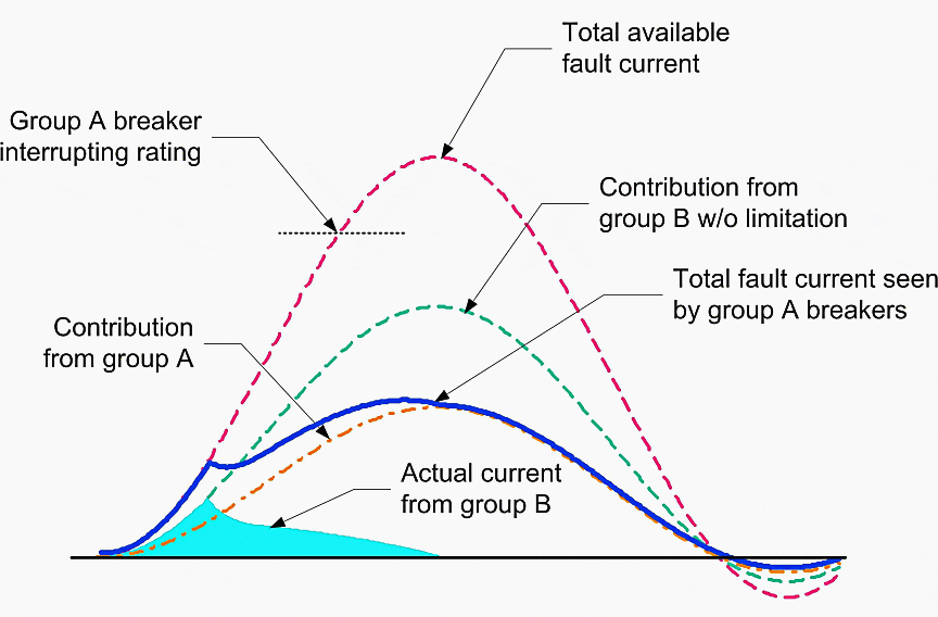
Figure 5 shows the contributions to the fault current from the sources on Bus A and Bus B. For ease of understanding Figure 5 it is assumed that the contribution from Bus B is larger. As can be seen in Figure 5 the current through the bus-tie is limited to a value much lower than the prospective short-circuit current from the sources on Bus B.

This current is limited much before the first peak of short-circuit current from Bus B occurs. The current limiter therefore reduces both the peak current and the interrupting current. After operation of the current limiter the only fault current to be interrupted by the circuit-breakers on Bus A is that generated by the power sources on Bus A.
Should a current limiter not have been installed in the bus-tie, the maximum short-circuit current would exceed the peak and interrupting capacity of the switchgear as shown in Figure 5.
Conclusion
Current limiters are a good solution to solve the problem of unacceptably high short-circuit currents in industrial sites.
Their use has been proven over the years and, in addition to clearing severe faults, they also reduce the strain on healthy equipment by limiting the peak currents and thus the mechanical stresses the downstream equipment is subjected to.
| Title: | How to reduce short-circuit currents in medium voltage applications by Terence Hazel, Schneider Electric |
| Format: | |
| Size: | 2.9 MB |
| Pages: | 6 |
| Download: | Right here | Video Courses | Membership | Download Updates |


Testing comment from a guide page.