
Distribution of fault currents
This guide primarily aimed at studying the distribution of fault currents, transferred voltages, and GIS very-fast-front transient overvoltage mitigation in power substations. The aim was to explain the relevant fault currents and their distribution to enhance the comprehension of earthing design.
Additional calculational parameters from the appropriate standards were also taken into account, including additional resistances, vertical earthing rods, and earthing conductors for improved soil conductivity.
These had not yet been incorporated into the company’s earthing design tool and were required for specific scenarios when conventional horizontal electrode earthing design methodologies may prove inadequate. The consequences and mitigation of transmitted voltages and very-fast-front transient overvoltage were examined from a grounding standpoint.
The principal conclusions and findings are presented below.
Current distribution and relevant fault currents
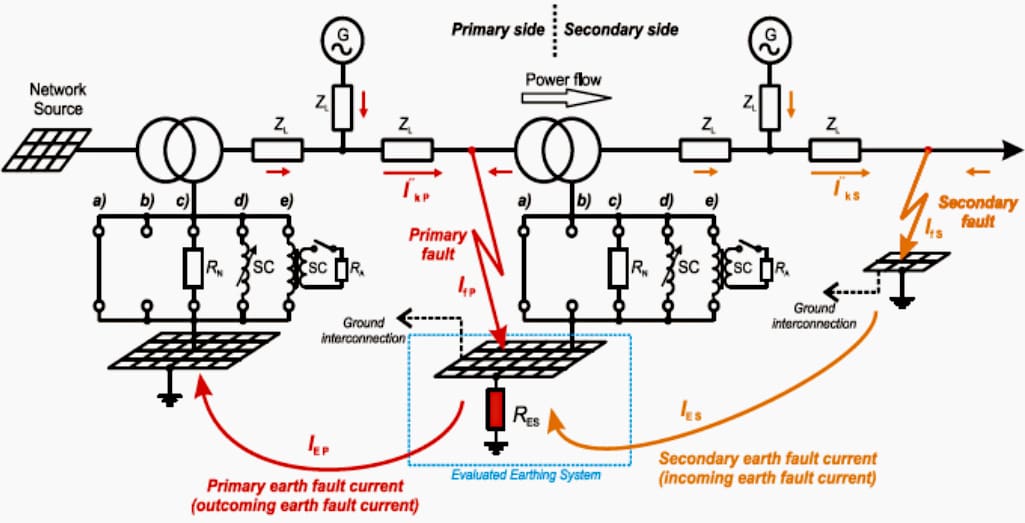
In various fault scenarios, the distribution of current between the ground, shield wires, tower earthing, cable sheaths, and the transformer neutral point was studied. The faults that cause the worst earth potential rise are the most important ones in substation earthing design.
Therefore, when designing the substation earthing, the station fault must be taken into account for overhead wires.
On the other hand, a fault inside the station with an isolated transformer neutral can be regarded as the worst-case fault scenario in order to simplify calculations. This saves engineering hours by providing the maximum earth potential rise with minimal design input.
Instead of using shield wires for overhead lines, the earthed cable sheath for underground cable systems offers a current path. The case of a fault at the station when the current is fed only from the other station must be taken into account when figuring out which current is causing the maximum earth potential rise inside the substation.
The reduction factor for the underground high-voltage cable cannot be utilized if it is only earthed from one side.
Figure 1 – Typical fault scenarios both for primary and secondary side
Installing a parallel earth continuity conductor is necessary for these single-point bonded systems in order to give the fault current a path.
This guide is intended to help designers gain a better understanding of the relevant currents and their distribution, particularly with regard to current flow to various structures and the use of reduction factors. Other fault scenarios, such possible rises between substations, may be pertinent to the design of other earthing systems.
The single-phase earth fault current, where the impact of shield wires or cable sheaths can be taken into consideration, is the fault current that contributes to the earth potential rise in the worst scenario that should be used in calculations. Although this current varies depending on the earthing system, the above r×I”k1 is applicable to the low-impedance earthing system that is most popular in Finland.
This is particularly true if there are notable differences in the shield wires’ reduction factors. The worst-case scenario, however, might be a fault at the station with the transformer neutral isolated, r×I”k1, in order to simplify computations. By not overcomplicating the calculation, the earthing grid will satisfy SFS 6001 criteria and save design hours.
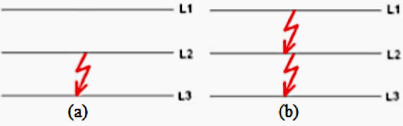
Figure 2 – Short-circuit types. (a) 2-phase short circuit, (b) 3-phase short circuit
Additional measures for difficult earthing conditions
It was determined that the company’s earthing design tool should incorporate a few more options for complex earthing settings. In challenging earthing situations, additional resistances may be useful, particularly if they are higher for shoes or surface soil.
For this reason, highly resistive materials can also be used to improve the resistance of the surface soil. Since the soil is often layered with significant variations in resistivity, the use of vertical earthing rods is also a pertinent technique, even though the outcomes may differ based on the soil parameters. Therefore, for determining if the application of vertical earthing rods is beneficial, knowledge of the soil structure is required.
Horizontal earthing electrodes to more conductive soil have been studied in addition to these techniques. If the area earth structure varies, this approach might be useful.
To further reduce the resistance at the station, a great earthing point is located near the substation in a region with good conductive qualities.
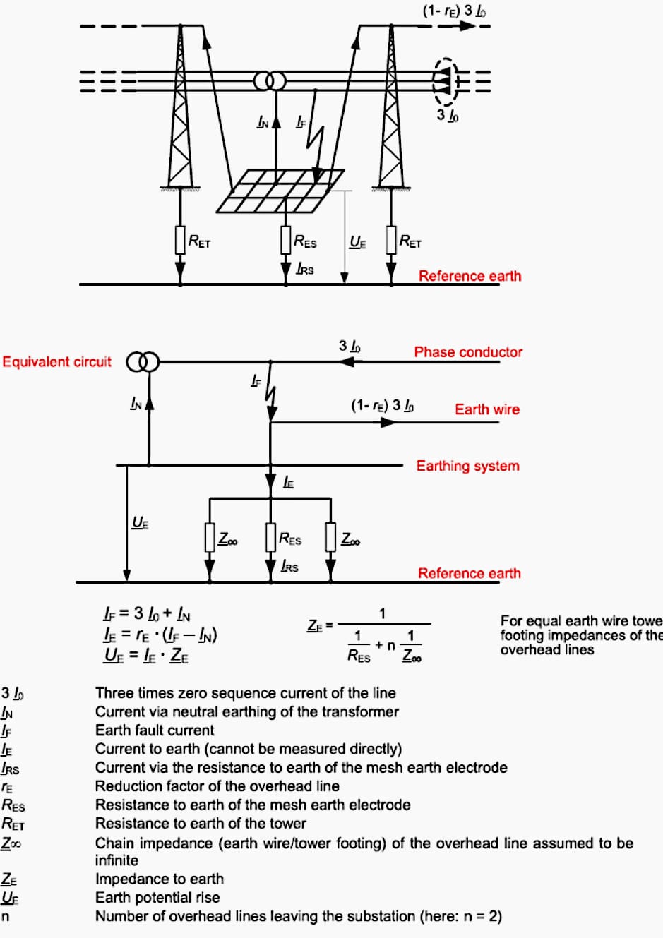
Figure 3 – Earth fault in a transformer substation with low impedance neutral (star-point) earthing
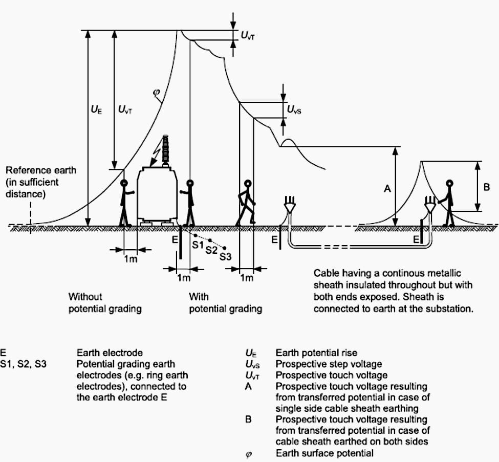
Transferred potentials
Transferred potentials were analyzed and found a risk for all substations, particularly those adjacent to residential zones. The SFS standard advocates for the segregation of various earthing systems to ensure that no dangerous voltages are transmitted outside the substation earthing grid region.
For systems over 50 kV, the standard mandates a separation of +100 m, which may be impractical to achieve in areas densely populated with structures near the installation. Potential magnitudes can be computed; however, obtaining reliable conclusions may be challenging because to the frequently unknown impedances of underground structures or their general configuration and placement.
If residential metals or other conductive constructions are extensive, a mathematical modeling approach should be considered.
This can provide a reliable indication of a secure perimeter, beyond which transferred potentials are deemed inconsequential. It is crucial to recognize that earthing potentials are hazardous not just to individuals but also to equipment, particularly communication networks.
This indicates that the limit values for communication equipment must be factored into the earthing design.
GIS very-fast-front transient overvoltage (VFTO)
Research was conducted on GIS very-fast-front transient overvoltage mitigation due to its potential to induce sparking, which raises safety concerns for the system. The findings indicate that the characteristics of VFTO prevent potential sparks from directly harming personnel. Nevertheless, subsequent occurrences may arise if personnel are taken surprised by the spark event, resulting in falls or trips.
Consequently, during commissioning or other site activities when the risk of sparking from switching operations exists, personnel must be instructed to prioritize safety and be prepared for potential incidents. The mitigation of the phenomena is a relatively new study topic, however numerous mitigation strategies have been proposed.
In earthing design, critical factors for mitigating very-fast-front transient overvoltage effects include frequent bonding and grounding of the system, maintaining short earthing connections, emphasizing the bonding of metallic enclosures, ensuring conductive platforms and operating metallic enclosures are at ground voltage level, separating power cable sheath grounds from enclosures, and preventing enclosure return current from flowing through any mounted current transformers.
Figure 4 – Touch and step voltages
Results
The objective was to enhance designers’ knowledge and comprehension of fault currents, reduction factors, and current distribution to consider the appropriate parameters. Consequently, these criteria were evaluated in a case analysis detailed in chapter 4.9, and this guidance functions as an effective resource for further project designs.
This tutorial indicates that the earthing voltage calculation tool can be enhanced to incorporate further measurements with the standard horizontal mesh earthing grid design.
This guide also provides valuable insights for earthing designers concerning the nature and mitigation of transmitted voltages and transient overvoltages.
Mechanical Check, Visual Inspection and Electrical Test of the Substation Grounding System (1)
Future research options
This guide’s scope was restricted by the huge subject matter of earthing systems. This guide generated additional questions that present valuable opportunities for future research. The low incidence rate of fault incidents in high voltage systems, coupled with the remote locations of substations, provides the analysis of risks and probabilities across many applications a compelling research topic.
This information might be integrated with data on earth fault time length to assess the risk factors associated with various sites.
The most interesting aspect would be to evaluate the earthing voltage outcomes across calculating software, manually computed values, and empirical measurements. This comparison would provide a clear idea of how the outcomes correlate and whether the program settings align with the established standards.
| Title: | A Guide to Substation Earthing Design And Understanding Dangerous Voltages by Samuel H. |
| Format: | |
| Size: | 1.9 MB |
| Pages: | 82 |
| Download: | Here 🔗 (Get Premium Membership) | Video Courses | Download Updates |
Suggested Reading – Analysis and design of schematic drawings
Fundamental concepts of schematic drawings: Going deeper into analysis and design intricacies
