
Soil Resistivity Measurements
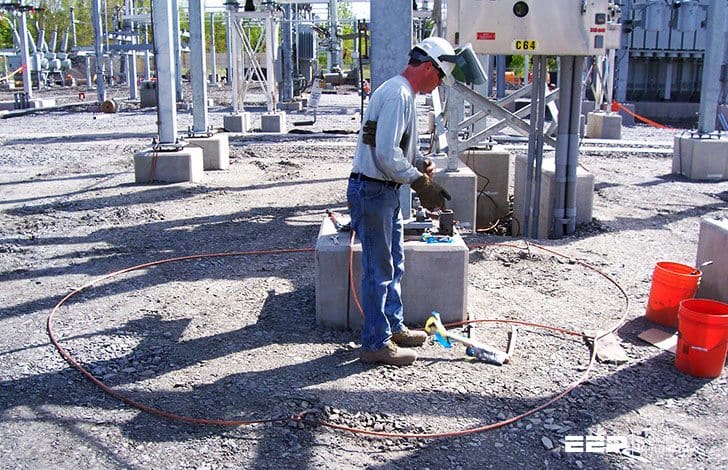
Before the design of the grounding system begins, soil resistivity measurements need to be taken at the substation. Stations with uniform resistivity throughout the entire area are rarely found. Thus, measurements should be made at multiple locations within the site.
Usually there are several layers, and each has a different resistivity.
If there are large variations, more readings should be taken at these locations. Lateral changes may occur as well, but in general the changes are gradual and negligible.
There are a number of measuring techniques. With two-point methods, rough measurements of the resistivity of undisturbed earth can be made. Three-point method or variation of depth method measured ground-resistance test several times.
Each time the burial depth of the test electrode is increased by a certain amount. But this method is not recommended if large volume of soil needs to be investigated.
Four-pin methods are the most accurate method of measuring the average resistivity of large values.
Wenner’s Four-Pin Method
The Wenner’s four-pin method is the most common. This method is also called the Equally-Spaced Four-Pin method.
This gives a value of the mutual resistance R. The Wenner’s four-pin method is shown in Figure 1 below.
The resistivity measurement records should include temperature data and information on the soil moisture conditions at the time that the measurements were done.
Also record all data available on any buried conductors already known or suspected. Buried conductors in contact with the soil can invalidate readings if they are close enough by altering the test current flow pattern.
The results are not greatly affected by the resistance of the test pins or the holes created by driving the test pins into the soil. A shortcoming of the Wenner method is that the magnitude of the potential between the two inner electrodes rapidly decreases when their spacing is increased to large values.
And often times commercial instruments cannot measure such low potential values.
| Title: | Guidelines to properly designed substation grounding system – Inna Baleva (A Project Presented to the faculty of the Department of Electrical and Electronic Engineering California State University, Sacramento) |
| Format: | |
| Size: | 1.00 MB |
| Pages: | 74 |
| Download: | Here 🔗 (Get Premium Membership) | Video Courses | Download Updates |

Wow, this article is pleasant, my younger sister is analyzing these kinds of things, therefore I am going to inform her.
When testing of transformers With impulse voltage generator according with IEC60076-3 Rule ,How to calculate the switching Impulse time from obtained graph in oscilloscope ,like T1,Td,T2(100us,200us,500us)
I am senior electrical engineers
I am from Egypt. Alexandria city