Switchgear access
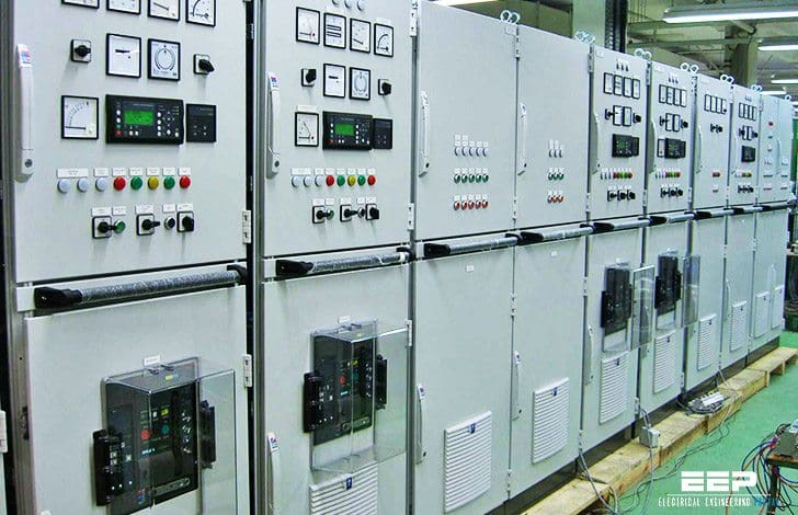
Cubicles may be front access only, rear access only or front and rear access. This has clear ramifications with regard to cable accommodation and access. What should not be overlooked with the Front access only configuration, is the fact that rear access may be available during the factory build period and that components – such as fuses, CT’s etc, are located such that they can be accessed when installed on site and in service.

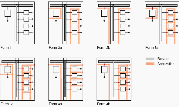
Forms of Separation
This essential aspect of switchboard design deals with the separation of live parts, functional units, terminals and glanding facilities and is defined in BS EN 60439.

Detailed information is also available in the BEAMA Installations’ “Guide to Forms of Separation”.
Fault Rating / Fault Level
A typical specification requirement where the supply is derived from transformer/s up to 2 MVA would be 50KA RMS sym 1 sec.
CASE: If a load has a large motor content this may become a source of regenerated energy during a short circuit fault on the system. The effect is that certain sections of the switchboard busbars have to carry the fault current “expected” from the supply source plus the regenerated (reverse current) from the rotating machines.
Fault rating or fault withstand capability is a safety statement that the equipment or device can without hazard to personnel, or equipment damage, operate or be operated up to that fault level and be suitable thereafter for further service, albeit in some cases at reduced load level.
In order to appreciate what has to be considered in the selection of components and the design of equipment to cater for the above requirements, it helps to have an understanding of what happens during a fault current transient period and the terminology used.
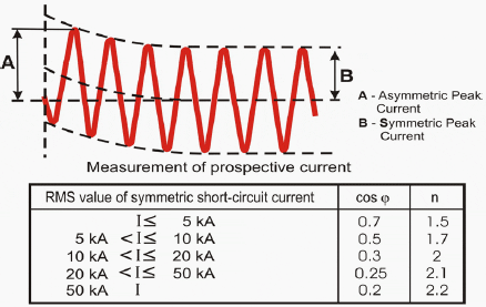
The following illustration graphically shows a typical short circuit current transient:

When a short circuit fault commences, an asymmetrical condition of the waveform initially occurs. A DC component, proportional to the fault circuit power factor effectively raises the sine wave zero axis thereby increasing the Peak Value of the current wave relative to the original axis during the first few cycles.
As can be seen from above illustration, the low power factor of the fault circuit (not to be confused with the distribution system PF) brings about an increase at 0.25 PF to 2.1 x RMS.
| Title: | Technical Considerations in the Specification of LV Switchboards – AF Switchgear, UK (afswitchgear.co.uk) |
| Format: | |
| Size: | 348.4 KB |
| Pages: | 17 |
| Download: | Here 🔗 (Get Premium Membership) | Video Courses | Download Updates |


There is no indication of the date of this guide published. It is informative, even though it is more than ten years behind time. The standard list in this guide BS EN 60439-1, 60947-2, 60529 and BS 7671 (16th edition) are all out of date/superseded. I strongly suggest readers refer to the latest publications e.g. BS EN61439-1, 61947-2, 61529 and BS 7671 (18th edition) etc to be aware of the “current” practices.
Che Kuan Yau (Singapore)
I have found this very informative and useful to improve the design of my panels. Thanks and best wishes.
How can we download these articles? They are blocked by omission of information needed to do so. Please help. Thanks very much.
This is not an article, but guide and you can download it.