

Introduction to the Commissioning Guide
The reliability of any electrical system depends significantly on both the equipment itself and how these pieces of equipment are interconnected. This introduction serves as a comprehensive overview of the NEDC Electrical System Commissioning Manual, a definitive guide designed to establish the condition and readiness of electrical equipment.
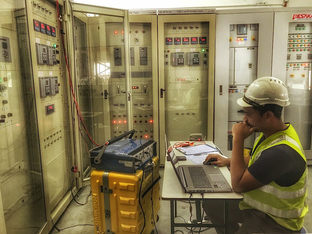
The manual outlines rigorous testing methods and criteria that contractors must follow, serving as a comprehensive guideline for field commissioning personnel.
Core Objectives and Commissioning Philosophy
The primary objective of the commissioning process is to demonstrate that each piece of interconnected equipment is appropriate for its intended purpose and fully suitable for commercial operation. Electrical testing of systems and their components serves two primary functions.
The first function is to verify that the equipment has been installed correctly and that both individual components and the overall system will operate as intended once energized. The second function is to establish baseline test data, which serves as a reference point for future assessments to detect any signs of equipment degradation over time.
A successful testing program relies heavily on a thorough survey of system equipment. Precise documentation of the power system must include a written system description, single-line diagrams, short-circuit and coordination studies, three-line diagrams, control and schematic logic diagrams, and cable block and interconnection diagrams.
Additionally, because primary equipment is crucial for overall functionality, a prioritized list of critical equipment must be established to indicate the sequence for inspection, testing, and energization.
The Four Phases of Commissioning
The commissioning methodology is strategically divided into four distinct phases to ensure safety, accuracy, and operational integrity before a system is brought online.
1. Pre-Commissioning Inspection:
This initial phase involves inspecting the installation to verify whether the work has been fully and properly completed to the extent that off-load commissioning tests can safely begin.
2. Off-Load Commissioning Tests:
This phase involves a rigorous program of tests associated with AC and DC circuit diagrams, including the secondary injection of DC relays and primary injections. It also encompasses high-voltage equipment tests on circuit breakers, switches, disconnectors, earth switches, transformers, reactors, busbars, and cables.
3. Pre-Energization Inspection:
Completed immediately before energizing the circuit, this phase utilizes a standard checklist to verify circuit naming and labeling. It ensures equipment phase connections match phasing diagrams, confirms no violations of safety clearances, and verifies proper earthing of all equipment.
It also requires confirming the removal of all test connections and ensuring the tightness of all cable terminations.
4. Post-Commissioning Inspection:
The final inspection confirms that commissioned equipment is ready for normal operational service. This includes verifying the removal of all temporary commissioning equipment and checking that all relay settings have been restored to their standard operational values.
Structured Test Methodologies
Electrical equipment is systematically evaluated through four specific categories of tests.
- Factory Tests: Performed by the manufacturer to prove the unit was built correctly and meets design specifications.
- Acceptance Tests: Run after installation but before first energization to confirm the equipment complies with project requirements.
- Routine Maintenance Tests: Scheduled at regular intervals during the equipment’s service life to track normal aging.
- Special Maintenance Tests: Carried out when a fault or abnormal condition occurs to help pinpoint the cause and extent of damage.
Before commencing any on-site testing, it is essential to confirm that the installation is fully complete, including the correct setting, wiring, and grounding of equipment.
De-energized component testing involves assessments such as checking pressure and fluid levels, conducting insulation resistance tests on equipment, measuring transformer turns ratios, and analyzing contact resistance.
All these evaluations are based on the requirements and recommendations set by international standards, including IEC and IEEE, and must strictly adhere to the operational manuals provided by the equipment manufacturer.
Safety Protocols and Hazard Mitigation
Because the commissioning process can involve serious hazards, safety must be prioritized at every single stage. Testing electrical equipment often involves the use of high voltages and currents, which pose significant safety risks to personnel and can potentially damage the equipment being tested.
Strict safety protocols must be established and consistently followed to protect testing personnel. At the appropriate point in the schedule, all high-voltage equipment must come under the utility’s official safety rules. The hand-over to these safety procedures must be carried out through a formal, documented process.
While direct voltage over-potential testing is generally considered non-destructive when performed by an experienced operator, contingency plans should be built into the testing schedule to address sudden insulation failures.
Stringent Documentation Requirements
A vital part of the commissioning process is to formally record both the managerial tasks and the technical tests performed. To meet strict quality-assurance standards, two separate sets of documentation must be prepared and regularly updated.
Commissioning Report:
This serves as the official managerial record. It must include a work program detailing each task with planned and actual completion dates. It also includes a schedule listing every commissioning test and a completion certificate signed by the commissioning team leader.
Commissioning Log:
This is the comprehensive record of the technical process. It comprises the completed commissioning test schedules, test certificates, inspection reports, and other relevant technical documents.
Comprehensive Equipment Guidelines
The manual is meticulously structured to provide clear guidance across various equipment types utilized within the NEDC network. It includes exhaustive summaries of equipment testing and scheme checks for major pieces of equipment like power transformers, capacitor banks, and 11kV/33kV switchgear.
For instance, the mechanical checks for an oil-filled power transformer require verifying the quality of the paint, checking lifting lugs, inspecting weld areas, and ensuring all groundings are securely connected.
CT testing requires verifying the magnetizing current, measuring winding resistance, and proving polarity through primary current injection. VT testing involves verifying that the star point of both primary and secondary windings is earthed, alongside rigorous ratio and polarity tests.
Furthermore, the document details the complete set of tests to be performed on each protection relay element, such as overcurrent, earth fault, and directional relays.
By adhering to these highly structured guidelines, check-lists, and testing formats, field commissioning personnel can ensure that newly installed electrical equipment has been safely transported, erected, and perfectly integrated into the power grid.
| Title: | A guide to testing and commissioning for field commissioning engineers |
| Format: | |
| Size: | 60.5 MB |
| Pages: | 625 |
| Download: | Here 🔗 (Get Premium Membership) | Video Courses | Download Updates |
Further Study – Biggest Mistakes in Analyzing Modern Substation Schematics


Excellent idea to issue such a manual for all testing engineers and managers. Thanks