Search

Premium Membership ♕

Experience matters. Premium membership gives you an opportunity to learn from experienced electrical engineers. Enjoy studying from low to high voltage!

Introduction to Differential Protection

Differential protection is a unit-type protection for a specified zone or piece of equipment. It is based on the fact that it is only in the case of faults internal to the zone that the differential current (difference between input and output currents) will be high. However, the differential current can sometimes be substantial even without an internal fault.

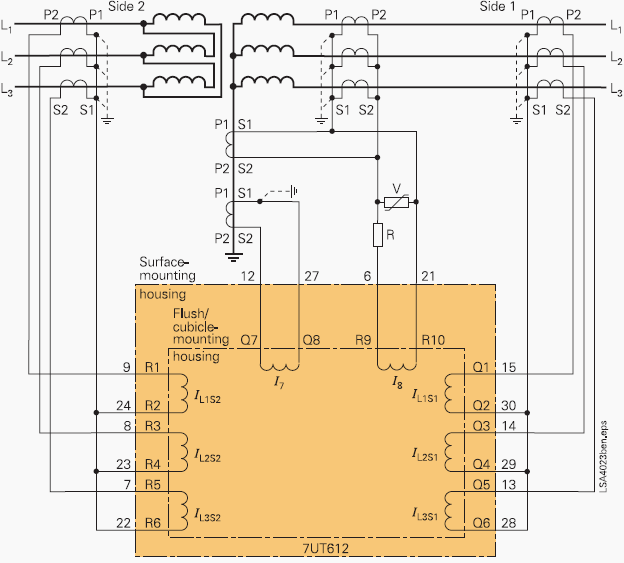
 SIPROTEC 4 7UT6 Differential Protection Relay for Transformers
SIPROTEC 4 7UT6 Differential Protection Relay for Transformers – Connection of transformer differential protection with high impedance REF (I7) and neutral current measurement at I8

This is due to certain characteristics of current transformers (different saturation levels, nonlinearities) measuring the input and output currents, and of the power transformer being protected.

With the exception of the inrush and overexcitation currents, most of the other problems, can be solved by means of the percent differential relay, which adds to the normal differential relay two restraining coils fed by the zone-through current, by proper choice of the resulting percent differential characteristic, and by proper connection of the current transformers on each side of the power transformer.

Percentage restraint differential protective relays have been in service for many years.

Figure 1 shows a typical differential relay connection diagram. Differential elements compare an operating current with a restraining current. The operating current (also called differential current), Id, can be obtained from the phasor sum of the currents entering the protected element:
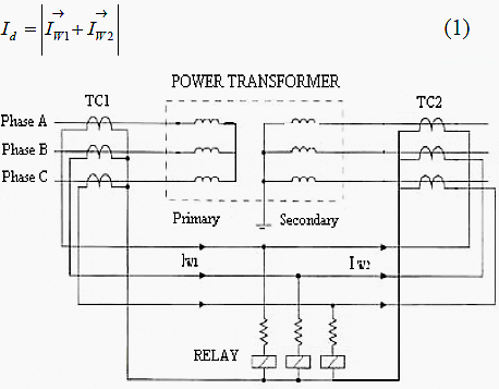
Figure 1 – Simple diagram connection for differential power transformer protection

Simple diagram connection for differential power transformer protection
Figure 1 – Simple diagram connection for differential power transformer protection

Id is proportional to the fault current for internal faults and approaches zero for any other operating (ideal) conditions.

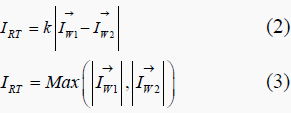
There are different alternatives for obtaining the restraining current, IRT. The most common ones include the following:
Restraining current (Irt)

Where k is a compensation factor, usually taken as 1 or 0,5.

The differential relay generates a tripping signal if the differential current, Id, is greater than a percentage of the restraining current, IRT :

Restraining current (Irt)

Differential relays perform well for external faults, as long as the CTs reproduce the primary currents correctly. When one of the CTs saturates, or if both CTs saturate at different levels, false operating current appears in the differential relay and could cause relay male-operation.

Some differential relays use the harmonics caused by CT saturation for added restraint and to avoid male-operations. In addition, the slope characteristic of the percentage differential relay provides further security for
external faults with CT saturation. A variable-percentage or dual-slope characteristic, further increases relay security for heavy CT saturation.


Cause Of False Differential Current

Specific events can induce a significant differential current to flow in the absence of a fault, and these differential currents are typically sufficient to trigger a percentage differential relay to trip. In such circumstances, the differential protection should refrain from disconnecting the system, as it does not constitute an intrinsic malfunction of the transformer.

Such events may result from the non-linearities within the transformer core. The following situations are examined below.


Inrush currents

The magnetizing inrush current in transformers is caused by any sudden alteration in the magnetizing voltage. While typically seen as a consequence of powering up a transformer, magnetizing inrush may also be induced by:

  1. Occurrence of an external fault,
  2. Voltage recovery after clearing an external fault,
  3. Change of the character of a fault (for example when a phase-to-ground fault evolves into a phase-to-phase-to-ground fault).
  4. Out-of-phase synchronizing of a connected generator.
The magnetizing branch, which symbolizes the core, functions as a shunt element in the transformer equivalent circuit. Consequently, the magnetizing current disrupts the equilibrium of the currents at the transformer terminals, leading the differential relay to perceive it as a “false” differential current. Nonetheless, the relay must maintain stability during inrush conditions.

Moreover, from the perspective of transformer longevity, tripping during inrush conditions is highly undesirable, as interrupting a purely inductive current produces significant overvoltage that can compromise transformer insulation and potentially lead to internal faults.

Title:Transformer Differential Protection Scheme With Internal Faults Detection Algorithm Using Second Harmonics Restrain And Fifth Harmonics Blocking Logic – Ouahdi Dris, Farag. M. Elmareimi and Rekina Fouad
Format:PDF
Size:259.3 KB
Pages:5
Download:Right here | Video Courses | Membership | Download Updates
Transformer Differential Protection Scheme With Internal Faults Detection Algorithm
Transformer Differential Protection Scheme With Internal Faults Detection Algorithm Using Second Harmonics Restrain And Fifth Harmonics Blocking Logic

Premium Membership

Get access to premium HV/MV/LV technical articles, advanced electrical engineering guides, papers, and much more! It will help you to shape up your technical skills in your everyday life as an electrical engineer.
50% Discount 💥 - Save 50% on all 90+ video courses with Enterprise Membership plan.

More Information

5 Comments


  1. Salim Rajan
    Apr 13, 2023

    Which is the fastest transformer protection?


  2. Thomas Nekhumbe
    Oct 13, 2019

    I would like to be updated with new schemes


  3. Thomas Nekhumbe
    Jul 26, 2019

    Am impressed by this information


  4. milad
    Jan 31, 2016

    what’s year of this article?


  5. NAGENDRA V R N
    Mar 26, 2015

    Good info provided.

Leave a Comment

Tell us what you're thinking. We care about your opinion! Please keep in mind that comments are moderated and rel="nofollow" is in use. So, please do not use a spammy keyword or a domain as your name, or it will be deleted. Let's have a professional and meaningful conversation instead. Thanks for dropping by!

14  ⁄    =  two

Learn How to Design Power Systems

Learn to design LV/MV/HV power systems through professional video courses. Lifetime access. Enjoy learning!

EEP Hand-Crafted Video Courses

Check more than a hundred hand-crafted video courses and learn from experienced engineers. Lifetime access included.
Experience matters. Premium membership gives you an opportunity to study specialized technical articles, online video courses, electrical engineering guides, and papers written by experienced electrical engineers.