System architecture and emulation
The system architecture here describes the generic conceptual model for the understating of the structure and functions of the system. The emulation imitates the behaviour of the system elements in normal and abnormal i.e. fault conditions for the system under design. All of the information analysed in this segment is utilized for designing the product which represents the functionalities and behaviours of the system.

Before going on with this, it becomes essential to understand the current design of the substation which is explained in next sections.
Secondary substation design
Based on the information gathered from the manufacturers, there are numerous available configurations of the substation. The configuration, size and rating, depend upon the network company for which they are being designed and they could be air or SF6 insulated.
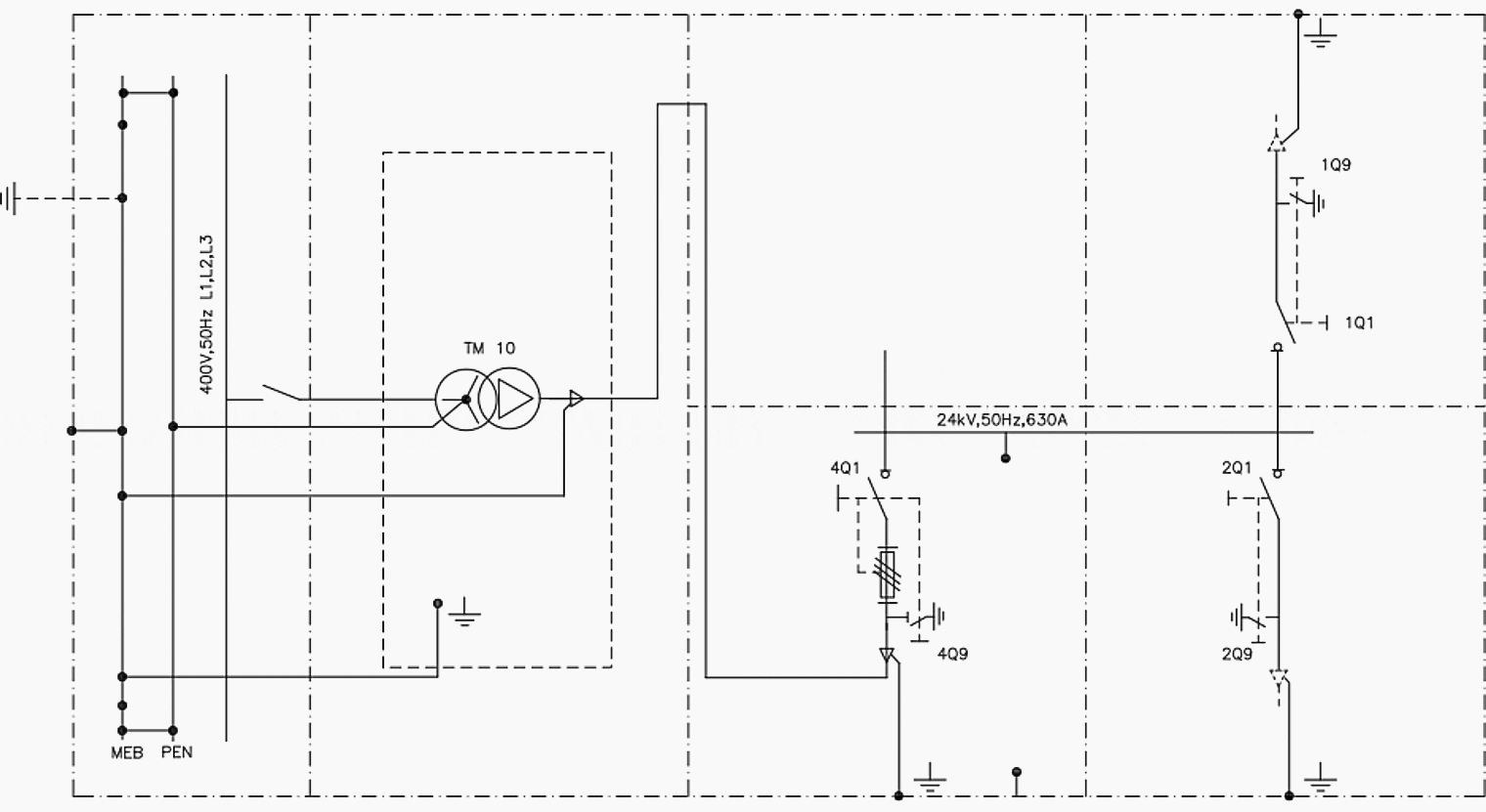
These configurations vary throughout Finland but the key design used dominantly is illustrated in Figure 1 below.
All of these switch-disconnectors can be made motorized using motor actuators for local/remote operation or can be replaced with CBs for better protection capabilities. Based on this substation design, the system architecture and its emulation are discussed in the upcoming sections.
Figure 1 – Power substation configuration 2+1

System architecture
From the requirement analysis conducted in the last chapter, it can be concluded that based on the need, the system will have all or some of the following functionalities:
- Monitoring
- Measurements
- Communication
- Protection
- Control
The control function is necessitated to operate the switches when needed and this operation may be manual or motorized. This may in addition be automated locally or via communication with the NCC which then requires energy storage for equipment operation in case of loss of mains.
The equipment/devices needed to achieve the above mentioned functions include but are not limited to:
- Instrumentation Transformers (Current and Voltage Transformers (CTs, VTs)) or sensors
- IEDs to take inputs from the CTs, VTs and other sensors to perform necessary action e.g. the IEDs could also be a relay with additional features
- Wired (optical fibre, RJ45 or other) or wireless (GSM, 3G, LTE, Radio and others) communication network through modems, routers or repeaters connected to NCC directly or via SCADA
- Motorised setup (Switch-Disconnectors, Circuit Breakers and others) for local or remote operation
The solution used for this research is discussed in the next section where this is emulated along with description of the features needed and utilized.
System emulation within network
For the purpose of emulation, a network illustration has been in PowerWorld software but as it lacks programmed control command capability; it can only solve network parameters of voltage, current and others and show the effect of switching in real-time but this switching cannot be done by following a pre-defined logic in the software.
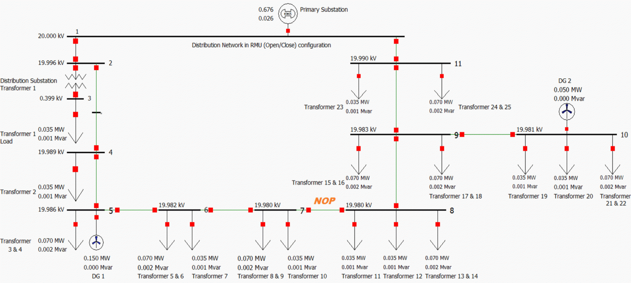
The single line diagram (SLD) representation of a sample network in RMU configuration is shown in the Figure 2 below.
Figure 2 – Emulated network in RMU configuration (click to zoom)

Figure 2 shows a MV distribution network in RMU configuration designed in PowerWorld. The bold lines represent the bus bars and the thin ones the MV distribution lines/feeders (overhead or underground) at 20kV. The down arrows represent the loads at each bus bar and the red squares are the switches.
There is one main generator feeding the whole network at Bus-1 through the PS and two Wind Generators which represent DG. Buses numbered 2 to 11 represent the SSs and are denoted as SS-2 to SS-11. Each SS has one incoming feeder, one or more distribution (MV/LV) transformers and one or more outgoing feeders. The representation of the transformer is made at Bus-2 only but it is present at each bus as a load.
Though the designed MV-network has a ring structure configuration, the operation is radial by creating a NOP. For this, the switches between Bus-7 and Bus-8 (switch at the outgoing of SS-7 and switch at the incoming of SS-8) have been assigned as a NOP to keep the automation as simple as possible.
Precaution! – For utilization of the NOP for restoration in the MV network, it has to be made sure that the LV network is in a radial configuration so that there are no interconnections between the LV feeders being fed from different MV feeders.
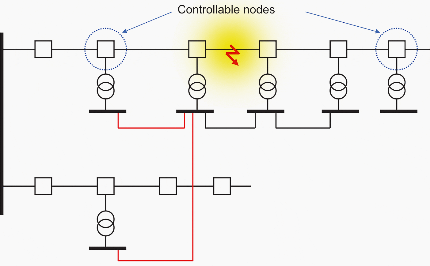
This interconnection known as the LV-couplings is shown in Figure 3 below:
Figure 3 – LV coupling beneath the RMU configured MV network

This was observed by E. Antila, P. Heine, and M. Lehtonen in “Economic Analysis of Implementing Novel Power Distribution Automation” in a project where the local LV network had a meshed grid structure. This can lead to a hazardous situation where the faulty location (feeder) is kept energized even after isolation of the fault from the MV network due to the bridge between the LV-couplings.
This has to be avoided at all costs and consequently it necessitates the LV-networks to be configured in a radial grid structure which becomes a prerequisite for successful implementation of the service restoration process in a RMU configured MV network.
| Title: | Design guide for upgrading existing secondary substations to be smart and intelligent – Gagandeep Singh |
| Format: | |
| Size: | 2.50 MB |
| Pages: | 110 |
| Download: | Here 🔗 (Get Premium Membership) | Video Courses | Download Updates |
Suggested Study – A Guide to Substation Earthing Design and Understanding Dangerous Voltages
A Guide to Substation Earthing Design and Understanding Dangerous Voltages

