
The substation in the study
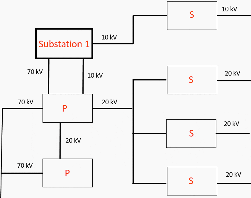
The substation is one of seven substations in the surrounding grid. The grid is separated from the rest of the regional grid and its small size and autonomy has made it attractive for testing of the centralized protection and control system architecture. The grid has a partially radial structure and is fed at two points, one for normal operation and the other as backup.
It has three voltage levels: 70 kV, 20 kV and 10 kV. A schematic of the grid is presented in figure below. The simple geometry of the grid means that, should the implementation of the new system into a single substation be deemed successful, the new system architecture could easily be tested on a grid where all of the substations were implemented with the new system.
The types of consumers in the grid are for the most part residential, with some larger plants and factories. Thus, the grid is made up of several, small consumers rather than a few, heavy loads.
This has the consequence that the load profile varies considerably during the course of a day, as the grid voltage spikes during mornings and evenings and drops during mid days and nights.
A grid with a wider distribution of consumers would have smaller variations, as the factories and offices where the residents go to work each day would compensate for the voltage loss during the middle of the day.
Single line diagram
Figure below shows a single line diagram of the substation. It is a compact way of representing a complex coupling scheme by way of symbols for common power system components such as transformers and power lines.
It also has the advantage of being capable of representing a three phase circuit as having only one phase.
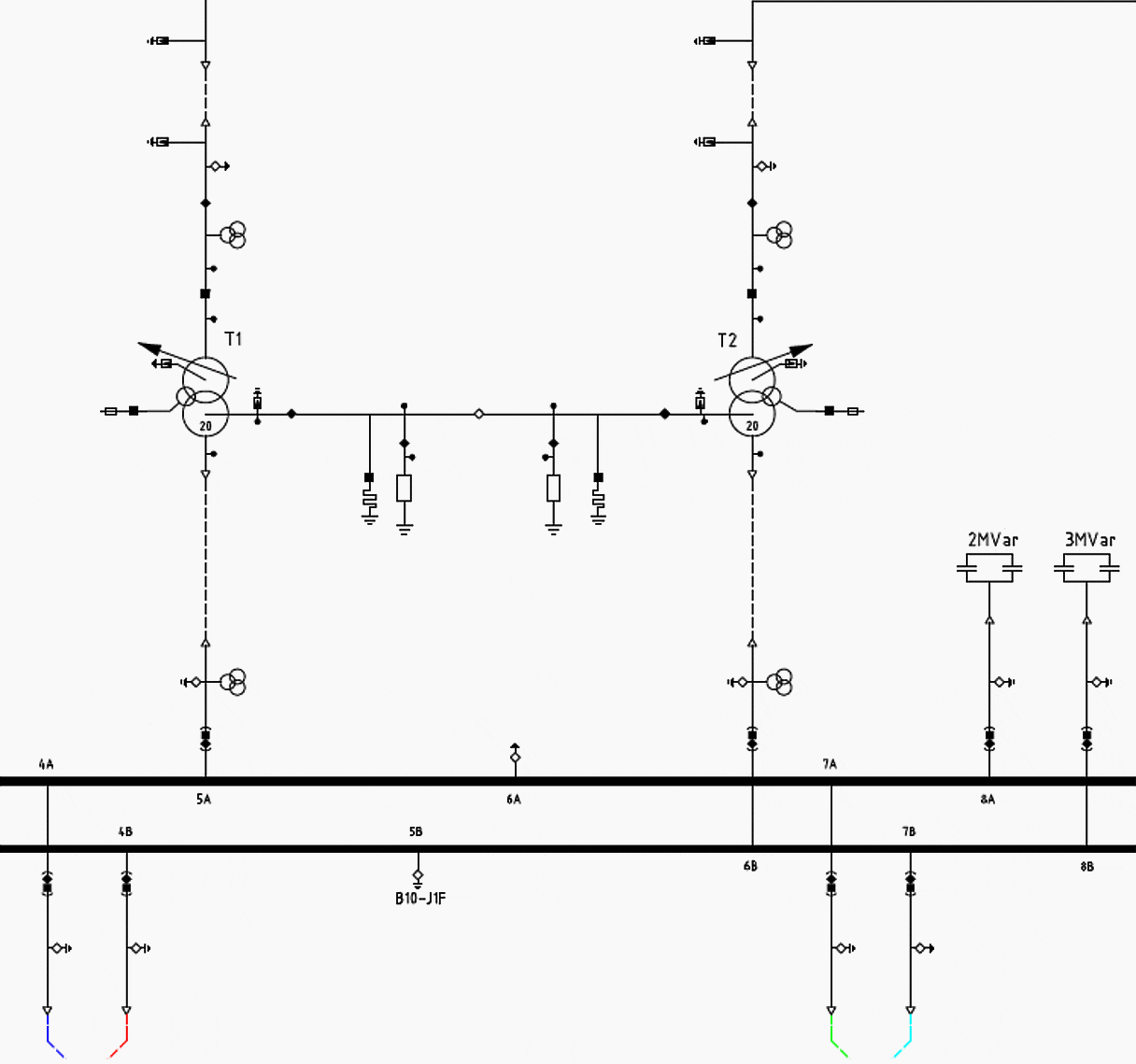
The main task of the substation is to transform incoming voltage from the transmission system at 70 kV to 10 kV for further urban distribution. As can be seen in the diagram, the incoming electricity is passed through a system of measuring and protection devices before encountering the transformers.
The 20 MVA transformers transform voltage from 70 kV to 10 kV before passing it on to a busbar with 18 outgoing lines which distributes it to the grid. 14 of these lead to neighbourhood consumers, two distribute the voltage to secondary substations and the last two are a back up connections to a primary substation.
Two capacitor banks with reactive loads at 2 and 3 Mvar are connected to the busbar to compensate for the reactive effect of the system. The transformers neutral is connected to reactive and resistive loads for compensating earth fault currents, as well as removing the risk for arcing earth faults.
| Title: | Centralized substation protection and control system for HV/MV substation – ENERGY NETWORKS ASSOCIATION |
| Format: | |
| Size: | 6.0 MB |
| Pages: | 81 |
| Download: | Right here | Video Courses | Membership | Download Updates |

i want learn etap.kindly call me on this mob no – 7291853765