
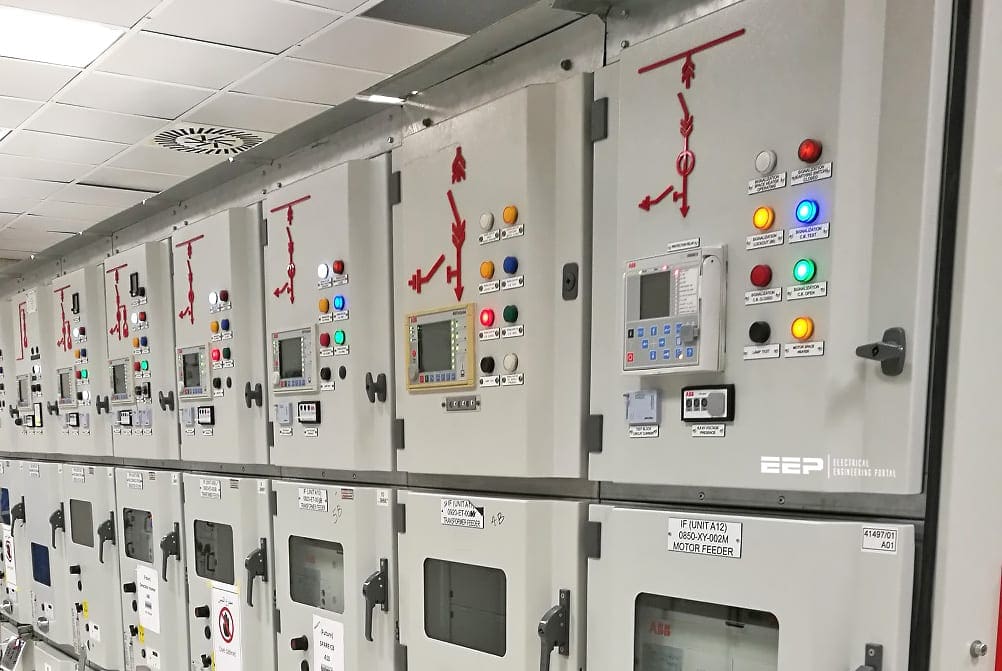
Protection Relays
The relay is a well known and widely used component. Applications range from classic panel built control systems to modern interfaces between control microprocessors and their power circuits or any application where reliable galvanic separation is required between different circuits. Altough considered to be a relatively simple component, the electromechanical relay and its technology is complex and often misunderstood.
History of relay
The earliest electrical relays were developed in the 1830s, as people began to recognize that such switches could be extremely useful. Historically, electrical relays were often made with electromagnets, which continue to be used today, although for some applications solid state relays are preferred. They key difference between electromagnetic and solid state options is that electromagnetic relays have moving parts, and solid state relays do not.
Electromagnets also conserve more energy than their solid state counterparts do.
Usage of relay
One of the reasons an electrical relay is such a popular tool for electricians and engineers is that it can control electrical output which is higher than the electrical input it receives. In the example discussed above, if the ignition connected directly to the battery, heavy duty insulated wiring would be needed to connect the steering column to the battery, and the ignition switch would also need to be much more robust.
A variety of circuits can be connected to an electrical relays. Relays can be used as amplifiers for electrical energy, as in the car example, and they can also connect to things like alarm switches, activating when a circuit is broken to trigger an alarm.
Many electrical failsafe systems utilize electrical relays which turn on or off in response to things like a current overload, irregular current, and other issues which may arise. These electrical relays trip to shut the system down until the problem can be addressed.
Besides exploring EEP’s guides and papers in this section, we recommend checking Romero Engineering’s free resources.
Browse guides and papers
Note that not all documents in this section are free to download. Navigate through sub-pages to discover all documents.


Hello we are a supplying company based in kenya we would like to inquire about some protection relays
Electrical relay diagram and p nid symbool book not available pls upload again.. Thanks
Very interested
I LIKE THE BOOK
Thanks very much for this site. Thank your whole team for putting up this site.
Thank you!, sir, your relay protection updating details have very useful for me for relay testing.
Today (11/19/2018) you published an article on protective relays polarity. I would like to download a copy. Thankyou.
Dear sir, i would have the guideline document related to scheme preparation of protective lines , transformer , generator etc.
I want to download this file
sir pls tell me how differential relay works ?
I have a crompton greaves drive in a equipment, i am unable to vary its speed from HMI. Also unable to find drive manual.
Can you help with probable solution
Thanks for information
Tahnk you very much for this website and for it’s team
Sir.
In India What % of T&D Losses are standardized.
Hello Jawaid,
Here is a short reply to your query..
Here in India 33kV, 22kV and 11kV level is considered as sub-transmission or HV distribution voltage level. Being a vast country distribution network and parameters differ widely from State to State and so does the T&D loss level. The loss level (which includes losses in HV lines and LT lines) in some pockets is around 10% and even less than that. However, it is as high as 30 to 40% in some rural and remote pockets.
We have two Thyro-A (AEG) in our substaion and both of them flashing on pulse inhibit.
we checked LED MESSAGES and have been detected that one of Frequency error or SYNC error can be occured, and SYNC error has more probability. If SYNC error be right fault, how can i remove it? Can you help me please?
Good work. thanks for the information
10+2 + iti electrician one year exp appertince plz sir my carreyear job requirements ho to sir plz bta na ya my number 9811092589
I am looking for Protection engineer who know completely about MIcom P 44 series distance Relays any body interested please contact me immediately
Salary package will be good
Name: koushal CS
Mobile: 9986101267
Email: [email protected]
I would like to know the reason for equi- potential wires getting disconnected at CT body end from main transformer incomer feeder. Feeder tripped on transformer differential & LV side restricted earth fault protection. Pls Explain…
yes it is possible, when ever equipotential ring is disconnected from ct there is a chance of occuring error on measuring of ct, actual current flow on ct and measured current on ct will differ in that situation u get the trip from both differential and ref protection.
please explain can we use measurement CT’s for protection relay ? if not so why ?
because of the ct winding always short suppose it is used for protection it will be open that time huge current flow through the ckt and it will damage the property or human body.
i had no idea about numerical relay, please tell full detail about that how to make setting,progarmming,configuration and progarmming logic. please sir,
thanks u very much, I am interested for particpate and to became member of this website.
HI,
please, can u give me the details of dry type transformer for the maintenance point of view.and also the over -under voltage relay…feeder protection relays..
thanking you..
As i know for Voltage Drop maximum allowable on VAC is 5%
What is the recommended voltage drop in Alternating Current{AC} and Direct current {DC}
Thanks for information
can any one share “pilot protective relaying by walter Elmore” or “Numerical Differential Protection by Gerhard Zeigler”
Thanks
Good site..Happy to see that the data are given thro industrial products(GE,Siemens,ABB like)
i want all information about relays.and specially information on ‘numerical relay protection for motor’
Congratulations for this website
This website is very helpful
thanks
B R I
Congratulations for this website
This website is very helpful
thanks
Good Job boss, really inspired especially application enginners like us….
You have done a excellent job. This website is very useful for begineers and even for expert as well.
Just joined after seeing reference on Linkedin and really impressed by the sites contents. Great work.
Sean
dear u really did great job ., i just want to know that ,can you provide me some elecrical formules for calculation for relay , like for didtance protection relay , or diff. protection relay
thnx a lot
Thank you for kind words Harjit! I wrote down your request, and I’ll try to find something.
BR
Congratulations for this website .
Gilmar
São Paulo -Brazil
Thank you Gilmar! Me and my team did a great efforts to make EEP to be like it is now.
BR,