
Ground source issues
The term “ground source”, as it is commonly used, implies a source for zero sequence current from a grounded neutral connection during faults or other system unbalance conditions. The term is a bit of a misnomer in that a grounded neutral is indeed not a source of zero sequence current, but rather a path for zero sequence current.

Even as a ground current path, the grounded neutral is not necessarily a ground source as it will be herein defined. The real source for ground fault current is the combination of the power system positive sequence generation to provide the fault current and the unbalanced fault condition.
Ground source importance towards the contribution of fault current
Figure 1(a) shows a generator or an equivalent source on the primary side of a transformer with the primary windings connected in delta and secondary windings connected grounded-wye. With a phase-to-ground fault on the primary side of the transformer the generator (source) will provide the current that must flow through the generator grounded neutral connection, which is usually a high impedance connection.
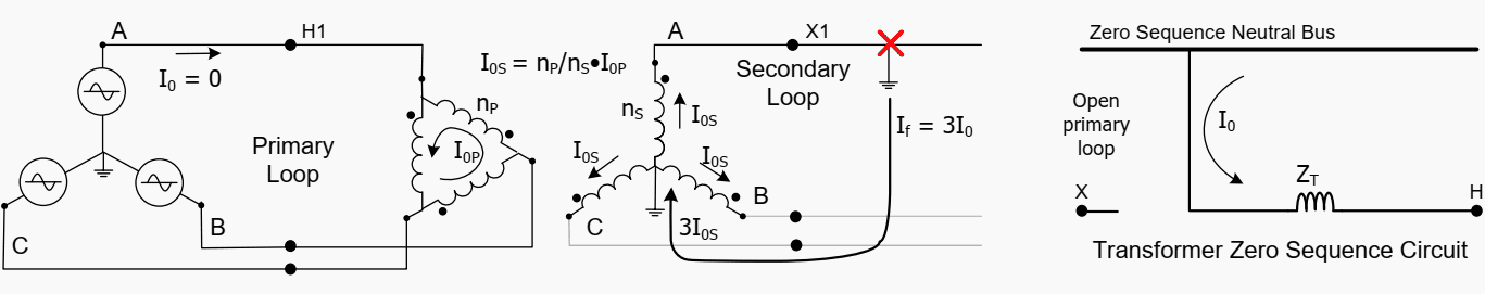
This is indeed a ground current path that meets the definition of a ground source. Ground (zero sequence) current cannot, however, be provided from the secondary system for this fault because there is no primary ground connection at the transformer to provide phase-to-ground amp-turn coupling through the transformer.
This coupling sets up the shunt ground path in the transformer equivalent zero sequence circuit.
Figure 1(b) shows the same configuration except the transformer is provided with wye-grounded windings on both the primary and secondary. The primary side, however, now has the ground connection to allow phase-to-ground amp-turn coupling through the transformer, i.e., nPI0P + nSI0S = 0.

Therefore, the per unit ground current is the same on both sides of the transformer regardless of the location of the fault. This results in a series coupled zero sequence current path through the transformer from the primary system to secondary system.
Figure 1(c) shows the configuration with a three winding transformer with two wye-grounded and one delta windings. This configuration provides both a series path to the primary source and a shunt path at the transformer for zero sequence current that will flow through the neutral during secondary ground faults.
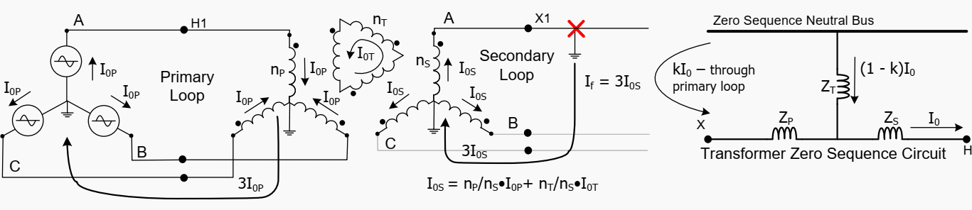
Considering the above discussion a ground source is therefore defined as a three-phase transformer or generator configuration with a grounded neutral connection that provides a shunt path in the zero sequence circuit for zero sequence current.
For the transmission system, ground sources are provided with either delta-wye or a zigzag transformer winding connections.
Distributed generation influence on transmission system ground sources
Distributed generation in the power system influences fault current and fault current distribution in a power system. The focus is how the distributed sources affect the magnitude of the ground fault current in the power system during a ground fault condition, so that proper coordination between ground overcurrent devices can be maintained.
Take the example system shown in Figure 2.
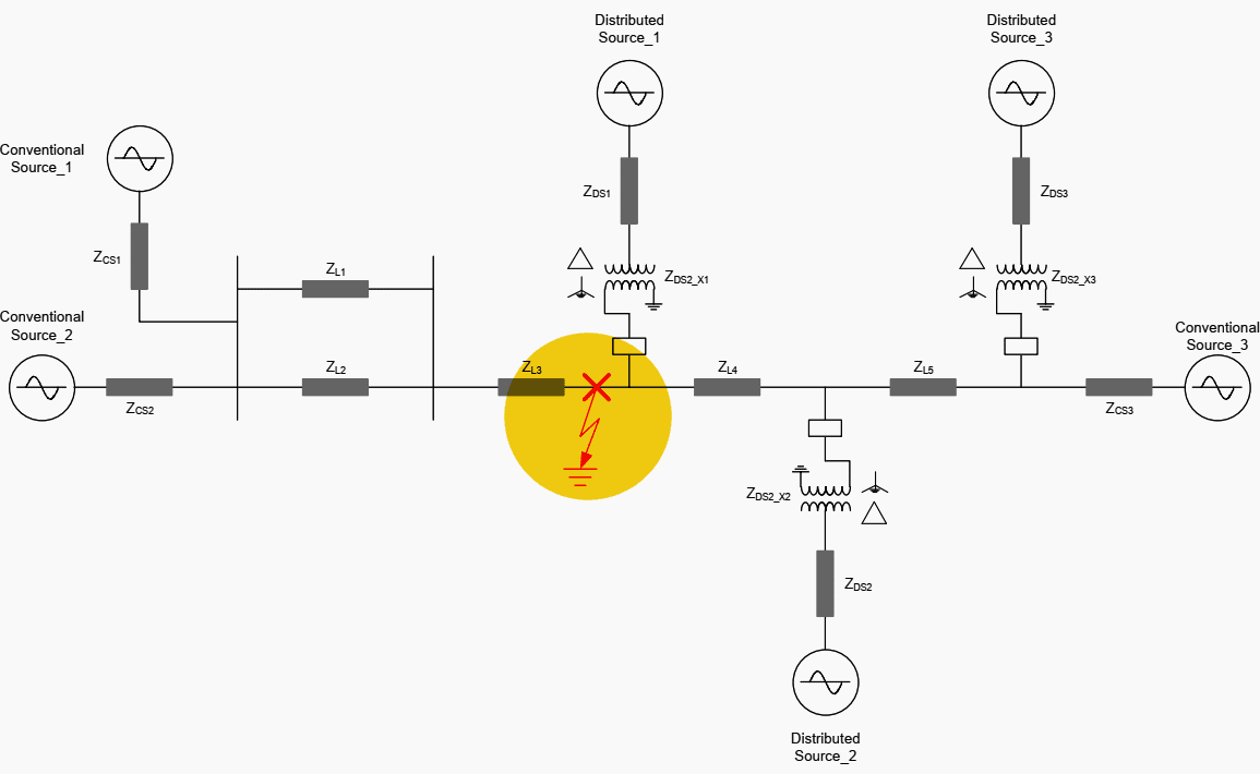
For a ground fault at the location shown in Figure 2 the zero sequence diagram is drawn as shown in Figure 3:
The distributed sources can be switched in and out of the system depending on the generation requirements of the power system. The conventional source will be considered as being in the circuit for the purpose of this discussion. Note that for this example the distributed sources have relatively high positive and negative sequence impedance when compared to the conventional sources.
In other words, the distributed sources contribute very little to the overall fault current whether they are in or out of service, and as such we can ignore them.
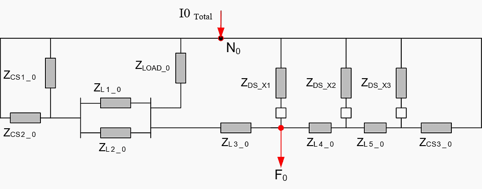
However, the distributed sources have relatively low impedance in the zero sequence network because of the wye-delta transformers used to connect them to the grid. Therefore, they have to be considered in the zero sequence circuit. Hence, the magnitude of I0Total is dependent on whether the distributed source is in or out of service.
The more distributed sources that are in service, the lower the overall impedance of the zero sequence circuit, and therefore, the higher the magnitude of I0Total.
| Title: | Applying directional overcurrent relays in ground fault detection for protection of transmission lines – Working Group D24 members: Don Lukach (Chairman), Rick Taylor (Vice-Chairman), Jeffrey Barsch, Ken Behrendt, Martin Best, Mike Bloder, Randy Crellin, Randy Cunico, Alla Deronja, Normann Fischer, Dom Fontana, Rafael Garcia, Gene Henneberg, Meyer Kao, Walter McCannon, Bruce Mackie, Alexis Mezco, John Miller, Dean Miller, Jim O’Brien, Cristian Paduraru, Manish Patel, Claire Patti, Elmo Price, Alejandro Schnakofsky, Mark Schroeder, Don Sevcik, Steve Turner, Karl Zimmerman, |
| Format: | |
| Size: | 459.7 KB |
| Pages: | 30 |
| Download: | Here 🔗 (Get Premium Membership) | Video Courses | Download Updates |
Suggested Reading – Three most common SCADA applications in MV/LV distribution systems you SHOULD know
Three most common SCADA applications in MV/LV distribution systems you SHOULD know
