
Earth Faults Hard to Detect…
The most common faults in a distribution network are earth faults, which can occasionally go undetected by conventional protection methods. When the earth fault current is too low to activate the sensitive earth fault protection, this could happen. Making sure the network is sufficiently secured against all kinds of faults—with earth problems being regarded as the most important—has always been a priority.

In certain cases, it has proved impossible to discover earth faults, which puts workers, the public, property, and plants at danger for injury. Reviewing the technologies that are available for use in the distribution power network to enhance earth fault detection and investigating ways to increase distribution network safety are the main objectives of this research project.
The project will provide an opportunity to explore other earthing fault protection techniques that are effective and potentially used by other utilities.
This research study will provide further insights into the improvements that can be made in the network in order to have a safe and reliable power system.
Figure 1 – Typical Earth Fault protection implementation
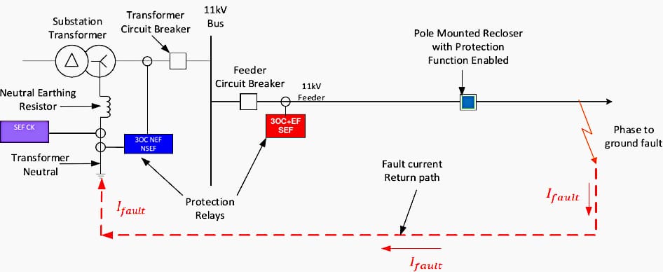
Earth Fault Protection Schemes
Presently, there are four main types of neutral earth connection of zone substation transformer star-point or delta connected winding being utilised in the Energex and Ergon distribution networks.
These are:
- Solidly grounded system
- Resistance grounding (Neutral Earthing Resistor)
- Reactive grounding (Neutral Earthing Reactors)
- Earthing transformers
The primary objectives of this research project were to:
- Investigate the different earthing system’s used in Energy Queensland’s distribution network.
- Investigate the benefits and challenges of existing and alternate earthing systems.
- Investigate the various forms of earth fault protection currently used by distribution network service providers
- Develop suitable distribution network models for the analysis of different earthing systems.
- Research and investigate alternate protection functions currently available in protective devices from suppliers / manufactures which can be utilised for detecting earth faults.
- Research and investigate the availability of new technologies that may provide better earth fault detection capabilities.
During the execution of this research project, analysis was carried out on the different forms of earthing systems currently being utilised and its implications on earth fault protection.
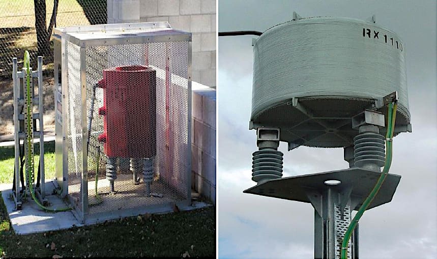
Figure 2 – Neutral earthing reactor in field
This study will form a vital part of research in an area which has its own challenges in meeting the various standards and industry practices to be able to provide a reliable and safe power network. It will provide an ideal opportunity to explore alternate forms of earthing systems and also other forms of protection which can assist in earth fault detection.
The successful completion of this research was important as it will result in:
- Exploring opportunities to improve safety in the network during an event of earth fault situation arising from broken conductor coming into contact with plant or property, human error leading into contact with power lines or other related causes.
- Possible solutions in detection of low values of earth fault current.
- Identification of alternate earthing systems and improved earth fault detection capabilities in protective devices.
If time and resources permit, further research detailed in the Project Specification in Appendix A will be undertaken.
Functions of Protection
Protection relays form an integral component of the power system network as they perform functions critical to the safe and reliable operation of the network. Some of these functions are:
- Detect faults and hazardous abnormalities in order to isolate the faulty section of the network within an acceptable time.
- Minimise danger to life and property.
- Reduce the extent of damage to network assets.
- Minimise the effect that a fault or abnormality has on the remainder of the network.
- Minimise the extent and duration of plant, equipment and circuit outages.
- Be reliable and secure to avoid mal-operation.
The provision of adequate protection to detect and disconnect elements of the power system in the event of fault is therefore an integral part of power system design.
Faults on the distribution network are typically considered as symmetrical and unsymmetrical faults. Symmetrical faults are severe balanced faults and occur less frequently in the power network. The two main types of symmetrical faults are, line to line to line to ground (L-L-L-G) and line to line to line (L-L-L).
Unsymmetrical faults are very common and occur more frequently in the distribution power network. The three main types of unsymmetrical faults are, line to ground (L-G), line to line (L-L) and double line to ground (LL-G) faults. Line to ground fault is the most common fault and causes unbalance in the power system.
Hence protection must be designed as such that it is able to protect the power system in all different fault conditions.
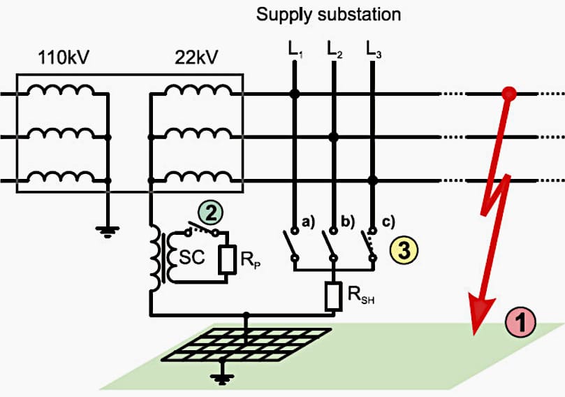
Figure 3 – Simplified scheme of MV supply substation with automatic systems for additional earthing
Functions of Earthing
The electrical earthing system is designed to provide safe and correct operation of the network under normal, earth fault and transient conditions. It is fundamentally required to provide safety to people, protect plant and equipment and support operational security. During earth fault conditions, large earth fault currents may flow via the general mass of earth en-route to the neutral point of the source transformer.
The earthing system, its components and earthing conductors shall be capable of conducting the expected fault current or portion of the fault current which may be applicable and without exceeding material or equipment limitations for thermal and mechanical stresses.
The earthing system is required to manage any hazardous potential differences to which personnel or members of the public may be exposed. It is required to ensure proper operation of protective devices such as protection relays and surge arresters to maintain system reliability.
Elimination of all hazards associated with earthing systems is rarely possible.
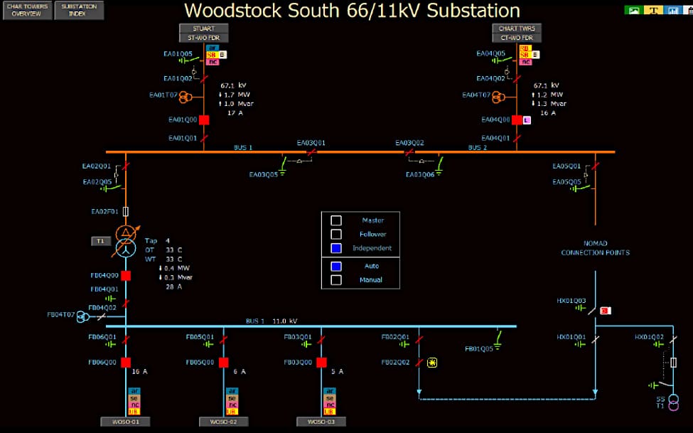
Figure 4 – Woodstock South 66/11kV Substation
During a fault involving earth, Earth Potential Rise (EPR) may exist on earthed assets, in these cases voltages in the form of touch, step and transfer potentials may be present on and around the installation. These voltages are defined as follows:
Touch potential: the difference between EPR of an earthing system and the ground surface potential at a distance of 1.0m. This is the difference between a person’s hand touching an energised object and their feet which is typically assumed to be 1.0m out from the energised object.
Step potential: the difference in ground surface potential between a person’s feet spaced 1m apart.
Transfer potential: the potential difference that may exist between the local earthing system and a metallic object (e.g. fences, pipes) bonded to a distant location that may be at a different potential.
The level of hazard present at a site during a fault or transient condition is site specific and determined by factors including but not limited to soil conditions, protection clearing times, fault current and current path. Under fault condition, the flow of current to earth will result in gradients within the path of fault current.
| Title: | Earthing Systems and Earth Fault Protection Study – Sanjay Narayan |
| Format: | |
| Size: | 12.20 MB |
| Pages: | 114 |
| Download: | Here 🔗 (Get Premium Membership) | Video Courses | Download Updates |
Suggested Study – Uprating and expanding existing power substations (good practice and recommendations)
Uprating and expanding existing power substations (good practice and recommendations)
