
Generator single line diagram
Generator Protections are broadly classified into three types: Class A, B and C. Class A covers all electrical protections for faults within the generating unit in which generator field breaker, generator breaker and turbine should be tripped. Clas B covers all mechanical protections of the turbine in which turbine will be tripped first and following this generator will trip on reverse power / low forward power protections.
Class C covers electrical protection for faults in the system in which generator will be unloaded by tripping of generator breaker only. The unit will come to house load operation and the UAT will be in service.
Various protections of this class are:
- 220 KV (HV side of Generator Transformer) busbar protections.
- Generator Transformer HV side breaker pole discrepancy.
- Generator negative phase sequence protection
- Generator Transformer over current / Earth fault protection
- Reverse power protection without turbine trip
Generator protection functions:
I – For insulations failures
- Differential
- Inter-turn fault
- Stator Earth Fault (95% & 100%)
- Rotor Earth fault (2 Stage)
II – For abnormal running conditions
- Loss of excitation (field failure)
- Unbalanced loading (negative phase sequence)
- Pole sleeping
- Overfrequency / Overspeed
- Overvoltage
- Reverse/Forward power
- Impedance/Over current back-up protection, etc…
III – For Generator transformer protections
- Differential protection
- Bias test
- 2nd harmonics restrained.
- REF protection
Figure 1 – Generator protection single line diagram
I – For insulation failures protection
1. Generator differential protection (87 G)
It is unit type protection, covering the stator winding for phase to phase faults due to breakdown of insulation between stator phase windings. This relay is not sensitive for single line to earth faults as the earth fault current is limited due to the high neutral earthing resistance.
For all machines of ratings 10 MVA and above, this protection shall be provided.
Diagram:
Figure 2 – Generator differential protection (87 G)
Settings:
- Pickup Value of Differential Current: 0.10 I/InO
- T I-DIFF> Time Delay: 0.00 sec
- Pickup Value of High Set Trip: 2.0 I/InO
- T I-DIFF>> Time Delay: 0.00 sec
2. Interturn fault protection of the stator winding (64GIT)
Formerly, this type of protection was considered unnecessary because breakdown of insulation between points on the same phase winding, contained in the same slot, and between which a potential difference exists, will very rapidly change into an earth fault, and will be detective by either the differential protections or the stator earth fault protection.
An exception is the generator designed to produce a relatively high voltage in comparison to its output and which therefore contains a large number of conductors per slot.
With the size and voltage output of generators increasing, this form of protection is becoming essential for all generating units.
Diagram:
Figure 3 – Interturn fault protection of the stator winding (64GIT)
The recommended relay is the high impedance relay having a setting range of 10-40% of rated current.
Settings:
- L-E Voltage of Faulted Phase Uph Min 110 V
- L-E Voltage of Unfaulted Phase Uph Max 110 V
- Uen> Earth Displacement Voltage 10 V
- T-DELAY TRIP Uen/3U0 0.50 sec
3. Stator Earth Fault Protection (0-95%) 64G1:
It is an over voltage relay monitoring the voltage developed across the secondary of the neutral grounding transformer in case of ground faults. It covers generator, LV winding of generator transformer and HV winding of UAT. A pickup voltage setting of 5% is adopted with a time delay setting of about 1.0 Sec.
For all machines of ratings 10 MVA and above this shall be provided. Relay application for this protection is mainly influenced by the method of stator earthing. Two methods are in common use.
- Resistor earthing
- Distribution transformer earthing
With resistor earthing, the fault current is limited to 200-300Amps while with distribution transformer earthing; it is limited to 5-10Amps. The latter method has the advantage of ensuring minimum damage to the stator core, but it is only practicable when the stator winding is directly connected to the delta winding of the main transformer.
The two schemes for stator earth fault protection (95%) are shown below:
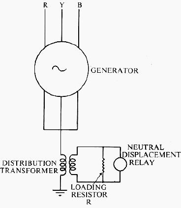
Distribution transformer earthing (High impedance earthing):
Earth fault protection is provided by connecting an overvoltage relay across its secondary, as shown. The maximum earth fault current is determined by the size of the transformer and the loading resistor R. The Relay used for this application is an inverse time or definite Time over voltage relay (Also known as neutral displacement Relay) with a setting range Of 2.5 to 20 Volts.
The relay is Provided with an inbuilt third Harmonic filter so as to avoid Unwanted operations due to third Harmonic currents and the Problems associated with transformer inter winding capacitance. It is possible to protect up to 95% of the generator stator Winding with this relay.
Figure 4 – Distribution transformer earthing (NGT)
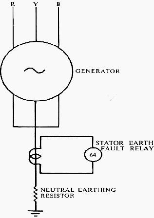
Resistor earthing(Low impedance earthing):
In the resistor earthed scheme, a CT is required in the neutral to earth connection, and the relay used is an inverse time current relay so that it can grade with other earth fault relays in the system. It also provides protection for the neutral earthing resistor. In this system, it is impossible to protect 100% of the stator winding. The percentage of winding protected depends on the value of the neutral earthing resistor and the relay
setting.
In the figure below, the percentage of winding protector is given for various values of earthing resistor at different relays settings, from 5-100 %.
Figure 5 – Resistor earthing(NGR)
Settings:
- Stator Earth Fault Protection: ON
- U0> Pickup: 4.8 V
- T S/E/F Time Delay: 0.20 sec
| Title: | Generator protection functions and test methods – VASUMURUGAN. R. |
| Format: | |
| Size: | 814.7 KB |
| Pages: | 22 |
| Download: | Right here | Video Courses | Membership | Download Updates |

very helpful to understand, thanks
I won’t to idea hi voltage protection &neutral can be fase and 440 volt and can be damage of my PCB and compressor pl. guide me
great help in understanding basics…
I am writing a review on the topic “Methods for identifying K3 and providing automatic reclosure of cable overhead lines.” I need articles, textbooks, and, in general, literature. I ask you to help!