
Settings for the protection relay
This guideline is entitled “Numerical Distance Protection Relay Commission and Testing” with the aims to calculate appropriate settings for the protection relay, configure the relay, install, commission and testing the entire protection.

Any kind of power system shunt fault results in customers being disconnected if not cleared quickly. Distance protection meets the requirements of speed and reliability needed to protect electric circuits, thus distance protection is used to a large extend on power system networks.
It is a universal short-circuit protection. Its mode of operation is based on the measurement of electrical quantities (current and voltage) and evaluation of the impedance towards the fault, which basically is proportional to the distance to the fault.
The objective of this exercise is to test a modern numerical relay for various faults within the distance zones under consideration.
Three zones are set: Zone one is an under-reaching instantaneous tripping zone set in the forward direction, zone two is an over-reaching zone with single time-delay also set in the forward direction and zone three is an over-reaching zone with double time-delay set in the reverse direction.
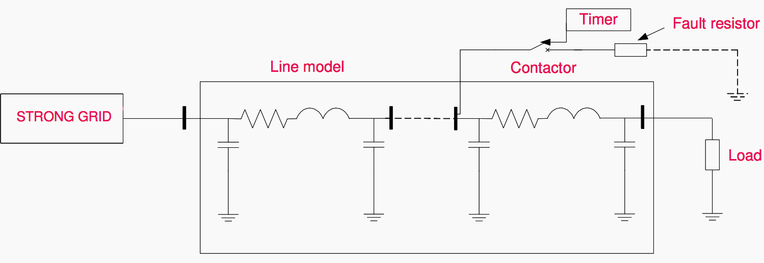
Power system model description
The power system model used in this exercise is a three-phase model of a 400 kV transmission, and two loads (two 9 kW three phase resistive loads). The entire model operates at 400 V.
The line model consists of six identical π-sections and each corresponds to 150 km of a 400 kV line. The sections can be connected arbitrarily in series or parallel.
The data for a real 150 km section are:
- X1 = 50.4Ω/phase,
- R1 = 4.17Ω/phase
- Zero sequence impedance Z0 = 3Z1
- The impedance scale of the line model is given as 1:53.2.
The numerical relay used in this laboratory is the Line distance protection relay REL 511*2.3 from ABB. The REL 511*2.3 is based on a full scheme distance protection function that detects both phase-to-phase and phase-to-earth faults and has a quadrilateral operating characteristics.
A separate general fault criterion with advanced characteristics is used for phase selection and as an overall measuring function, which increases the total operating security and facilitates remote backup applications.
Relay parameters:
- Current: Rated Ir = 1A
- Nominal range: (0.2 -30) * Ir
- Operative range: (0.004 – 100) * Ir
- Permissive overload: 4 * Ir continuous, 100 * Ir for 1 s
- Voltage: Rated Ur = 110V,
- Nominal range: (80 -120)% of Ur
- Operative range: (0.001 – 1.5) *Ur
- Permissive overload: 1.5* Ur continuous, 2.5* Ur for 1 s
- DC supply for relay: 48 – 250 V.
Figure 1 above shows the line model used for the laboratory.
| Title: | Testing And Commissioning Numerical Distance Protection Relay – Hung Manh Tran and Henry Akyea (Thesis for the Degree of Master of Science, Chalmers University of Technology Göteborg, Sweden) |
| Format: | |
| Size: | 9.9 MB |
| Pages: | 101 |
| Download: | Right here | Video Courses | Membership | Download Updates |

While tripping feeders dip in the voltage of transformer observed by other consumers feeding with this transformer. Please suggest measure to avoid this dip as feel by other consumers.
Why does a 100mva transformer trip itself due to internal faults by sensing itself the faults like fault current internal not by any external fault current ..
For example an 100mvs transformer connected with 10feeder lines and if one feeder got trip on efr fault y phase, the transformer should not trip but it trips by sensing internal current fault sensing itself n tripping itself ..
Kindly ans for this .. experts ..
Which rely trip the transformer? I think it would be Differential relay. So if it is…. It’s operating on through fault. Change the star point of HV or LV side Differential core physically or from rely. 2. HV and LV Differential CT cores should be ground at one end either from outside or inside the panels.
dear sir
could you please tell us how to set overload protection RELAY TYPE MICOM P220 for induction motor rated 11kv , 67A