
Plant protection system functional testing
Protective circuit functional testing, including lockout relay testing, must take place immediately upon installation, every 2 years thereafter, and upon any change in wiring. If applicable, documentation is required detailing how verified protection segments overlap to ensure there is not a gap when testing the total protection system.
The protection circuits include all low-voltage devices and wiring connected to: instrument transformer secondaries, telecommunication systems, auxiliary relays and devices, lockout relays, and trip coils of circuit breakers.
Protection circuits also may include all indicators, meters, annunciators, and input devices such as governors, exciters, and gate closure control circuits if required for the correct function of the protection system.
Although testing of individual components may take place on a regular basis (e.g., relay calibration and lockout relay testing), it is essential to test the entire protection circuit, including wiring, and all connections from “beginning to end” to ensure integrity of the total circuit.
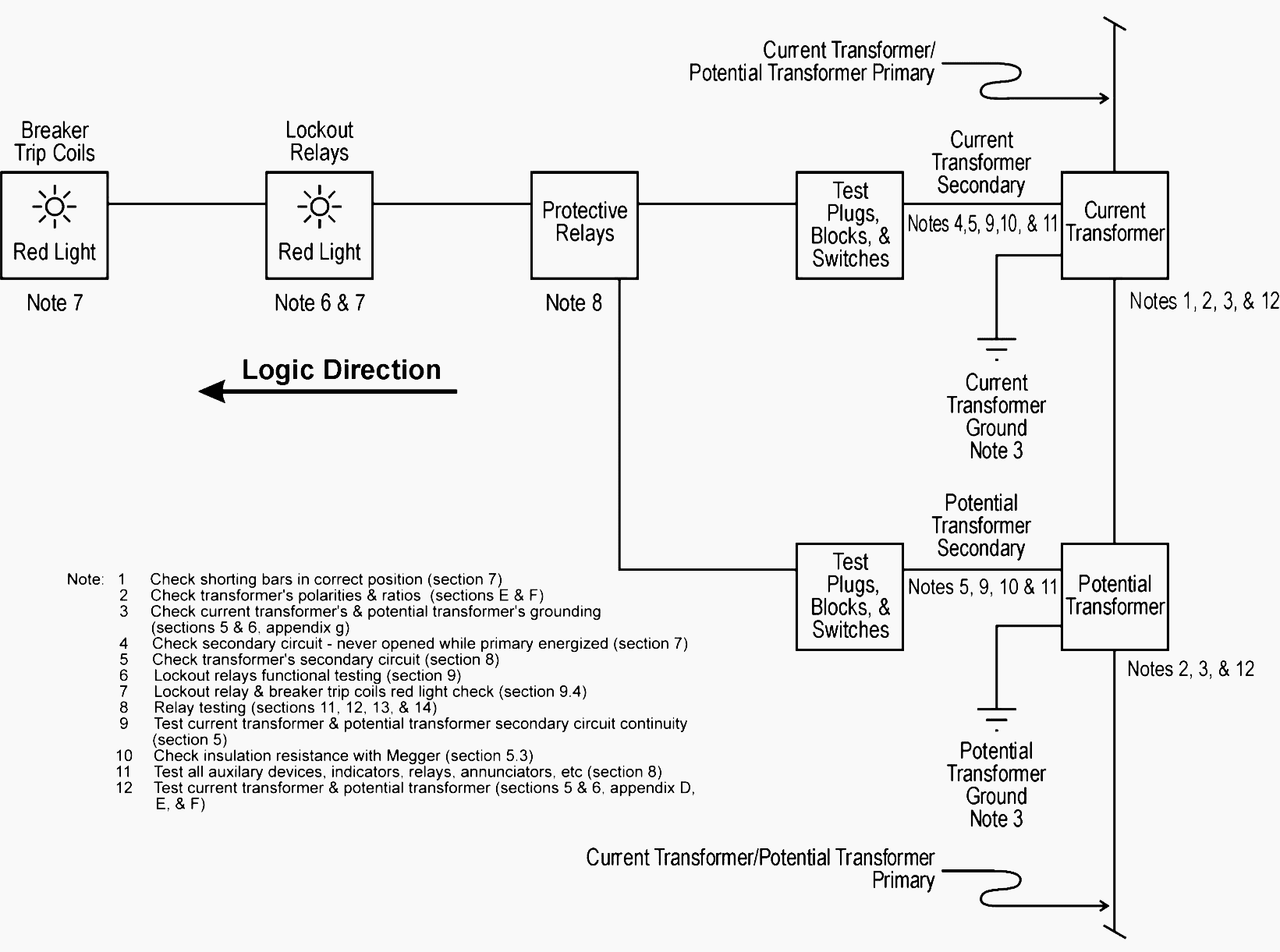
Critical examples of these circuits include, but are not limited to, the generator protection (86G), generator differential protection (86GD), transformer differential protection (86KD), and unit breaker failure protection (86JF) circuits. See the block diagram, figure 1.
Primary and secondary injection test techniques
One approach to test the total protection system is to use primary injection techniques (see appendix H) that trigger protective relays and lockout relay, trip circuit breakers, and initiate annunciations and indications.
This technique also tests the CT or PT ratios, polarity, and phasing. Verify PT and CT secondary grounding in separate tests. If primary injection is not possible, use secondary injection techniques.
These techniques locate wiring errors, insulation failures, loose connections, and other problems that go undetected if only relays are tested. Test each part of the entire system at least one time. For example, on a three-phase overcurrent relay, it would be necessary to inject a current at the phase A CT and verify that the relay and associated breaker trip.
The phase B and C CT also would need to be tested in a similar manner; but the trip lead from the relay may be lifted, since this part of the circuit already was tested.
| Title: | Operation, maintenance, and field test procedures for protective relays and associated circuits – U.S. Department of the Interior Bureau of Reclamation Denver, Colorado |
| Format: | |
| Size: | 1.7 MB |
| Pages: | 123 |
| Download: | Right here | Video Courses | Membership | Download Updates |

engineering portal is a learning platform keep up
i like the portal because its helps me improve my electrical carrier thanks
Good information about operation & maintenance of electrical equipments.