Fault types and protection philosophy
The challenge of having a good location of ground faults in power distribution networks drives the protection systems to use different methods and algorithms. The knowledge of the ground fault position allows having selectivity between the protection systems installed at different positions in the electrical network and removing from service only the zone with defect.

In this way, the grid can withstand faults with different severity and remain stable. Different methods to detect, locate and clear faults up with total selectivity are described then.
All power system elements are subjected to faults: generators, transformers, busbars, transmission lines, distribution feeders/lines and loads.
The main causes of faults are:
- Causes of faults: Failures of isolating (permanent /transient overvoltages, switching, lightning strokes, etc).
- Insulation aging: may cause breakdown even at normal frequency and voltage ranges.
- External object: tree branch, birds, rodents, etc. may span either two power conductors or a power conductor and ground.
If the time that the fault is present is considered, those can be classified in:
Permanent – created by breaking insulators and conductors, objects falling on the ground/phase conductor, etc. Once the protection systems have cleared up the fault, the system is inactive while the damage is not solved.
Transient – short duration created normally by over voltages (flashover across the insulation). The protection systems normally clear up the fault very quickly in less than 200 ms and then an autoreclosing manoeuvre is carried out to restore the power supply and stability.
Semi-transient – created by external objects. This is a problematic fault as the protection systems send tripping and reelosing commands several times. This situation creates high stress in the network as the circuit breakers are switched on under fault conditions
In an easy way, the main effects of the faults in electrical networks are:
- Reduction of the voltage profile on the entire electrical system affecting all types of connected loads.
- There is a frequency drop that may lead to instability among interconnected, synchronously running generators, which, unless halted by suitable means, result in cascade tripping of generators.
- Appearance of voltage imbalances and negative sequence currents, which produce overheating in the power elements involved in the fault and close to it.
In order to clear up faults, the basic and primary function of relays is to detect faulty elements in the electrical network and remove them from service as quick as possible to keep security and reliability in the rest of the power system as well as power supply.
Protection relays send tripping commands to the corresponding circuit breakers whereas the use of fuses as protection systems don’t. Using fuses, both the detection of the fault and the current interruption are done simultaneously.
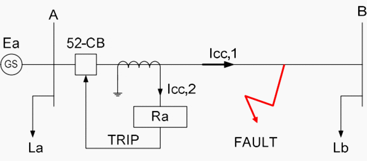
In this case, the overcurrent protection relay Ra measures a fault current Icc,1 and clear it up.

In DEF networks, the protection systems eliminate all possible faults that could happen between the installations of CT’s at both ends of the line. Figure 2 indicates the tripping orders given by protection relays Ra and Rb to their respective circuit breakers when a fault happens again at any position in the line that connects busbars A with busbars B loaded with loads La and Lb.
In this case, the overcurrent protection relays Ra and Rb measure fault currents Icc,a. and Icc,b.

From Figure 1 and 2 it has been seen implicitly the protection zone covered by protection relays Ra and Rb. The protection zone is the area of responsibility for the protection system to eliminate faults that arise in such zone as soon as possible. All protection relays generate their own protective zone, normally called ‘primary protected zone‘. Any fault that occurs inside the protective zone, initiates the operation of the protection system. In this case, the fault is known as – ‘internal fault.
However, if a fault takes place outside the protective zone, it does not initiate the operation of the protection relay and the faults is named as ‘external or through fault‘.
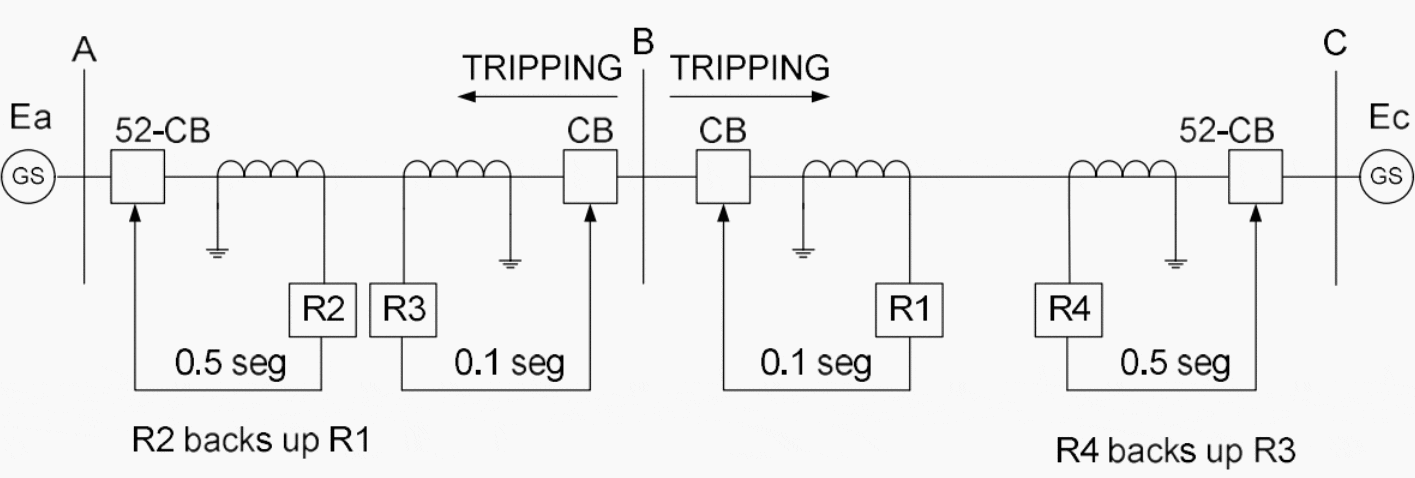
The first protection system is called ‘primary protection‘ and the second protection system is named ‘back-up protection‘. The principle of the back-up protection system is that there must be at least a second opportunity to clear up faults.
If the primary protection fails to eliminate the fault condition, another protection system should do it and trip its 52-CB associated after the tripping adjusted time at the primary protection system had expired.

Figure 3 explains in an easy way the back-up principle. When a fault happens in line B-C, the first protection system to clear the fault up is the protection relay Rb once the tripping time set has expired as the fault has happened in the protection zone of relay Rb. If this relay fails to eliminate the fault, the back-up protection relay Ra will have to take up the responsibility of eliminating such fault.
For this purpose, the protection relay Ra must be set adequately to read the fault current and trip in a longer time than the time adjusted in protection relay Re, that means that tRa > tRb.
Different causes of primary relaying failure are:
- Failure in CT and/or voltage transformers (VT’s) due to had design or wrong characteristics that drive them to deliver inadequate current or voltage signals to the protection relays.
- Failure in the leads from CT/VT to the protection relays with wrong connections that can cause bad operation performance in the protection relays.
- Failure of the relay to operate due to inadequate maintenance: modems protection relays include a ‘watchdog output contact‘ that allows having a signal that indicates whether the protection relay is in full operability or not.
- Failure of auxiliary power supply.
- Failure in the trip circuit: actual protection relays include the functionality known as ‘trip circuit supervision‘. Normally the resistance of the tripping coils of the circuit breaker is checked continuously injecting a low value current and measuring the voltage across such tripping coils.
- Mistake of the circuit breaker to open, perhaps due to mechanical linkage failure or welded contacts. Those contacts become welded when the circuit breaker is reclosed on a fault condition.
- Wrong settings definition for the protection relays: sometimes the settings introduced in the protection relays are inappropriate and the fault is unable to be eliminated. A proper network and settings coordination studies should be developed to avoid this possibility.

There are two main types of back-up protection systems: Local and Remote. Local back-up has the disadvantage that if there is a failure at the auxiliary power supply, it makes local back up useless unless different auxiliary power supplies are installed.
As recommendation it can be said that anything that might make the primary protection system to fail, should not cause the back-up protection system fails too. Remote back-up is normally preferred.
| Title: | New protection methods for power cables used in both AC and DC grids – Ricardo Granizo Arrabe; Master in Electrical Engineering by Universidad Politecnica de Madrid |
| Format: | |
| Size: | 6.8 MB |
| Pages: | 264 |
| Download: | Right here | Video Courses | Membership | Download Updates |


Hi, I love my job: safty Protecting & diagnosing any leackage & safety because I’m not the only one in site. Everyone needs a smile 8n any safety
Good