Methods of microgrid protection
Islanding detection is one of the critical issue to design an effective protection system. That’s why microgrid protection is analyzed by considering two aspects: islanding detection and fault current protection in grid connected and islanded mode.

A feasible protection technique has to be implemented for the microgrid in a manner that maximum portion of the network can be served during any type of fault by isolating the faulty part of the network. It means that an effective protection scheme should design with capability of minimum outage and maximum reliability.
Protection systems are designed in two layers: primary protection system and backup protection system. Primary protective devices act in case of any short circuit fault within its coverage area. However, backup protective devices provide support in the failure of primary protection scheme.
A very simple protection is employed using overcurrent relay and fuses in traditional radial feeder network.
Hence, it is excessively challenging to design a proper protection scheme to meet above issues. The next sections are about techniques for protecting microgrid in both operating mode.
Adaptive protection for microgrid
The presence of DG units throughout the distribution network changes the fault level and strength of fault current. Hence, the reconfiguration of protective devices in terms of power rating is required. This section presents an adaptive protection plan that can efficiently response towards the changes brought by the implementation of DG units in microgrid network.
The definition of an adaptive protection is as follows: “an online activity that modifies the preferred protective response to a change in system requirements or conditions”.
The following technical requirements are needed for real application of adaptive protection system in microgrid network:
Requirement №1 – Implementation of digital and directional over current relays instead of traditional solid-state and electro-mechanical relays or fuses which do no have any selectivity feature and directional element.
Requirement №2 – The digital microprocessor-based relays must have different settings, especially for different fault current characteristics and their settings can be changed from remote location or locally.
Requirement №3 – The communication infrastructure between relays and microgrid controller has fast data transmission rate with high security. A standard protocol such as IEC 61850 should be used for proper communication to ensure a task completed successfully.
Figure 1 illustrates a communication assisted microgrid central controller (MCC) based MV/LV microgrid network including primary switching devices. The assignments of MCC is done by a control station computer or a person-controlled PC and a programmable logic controller (PLC).
The blue lines in Figure 1 shows the communication link between microgrid components with MCC. The protocol used in this communication is IEC-61850. Digital directional relays can communicate with MCC through this link and MCC also able to updates their settings shown in Figure 1.
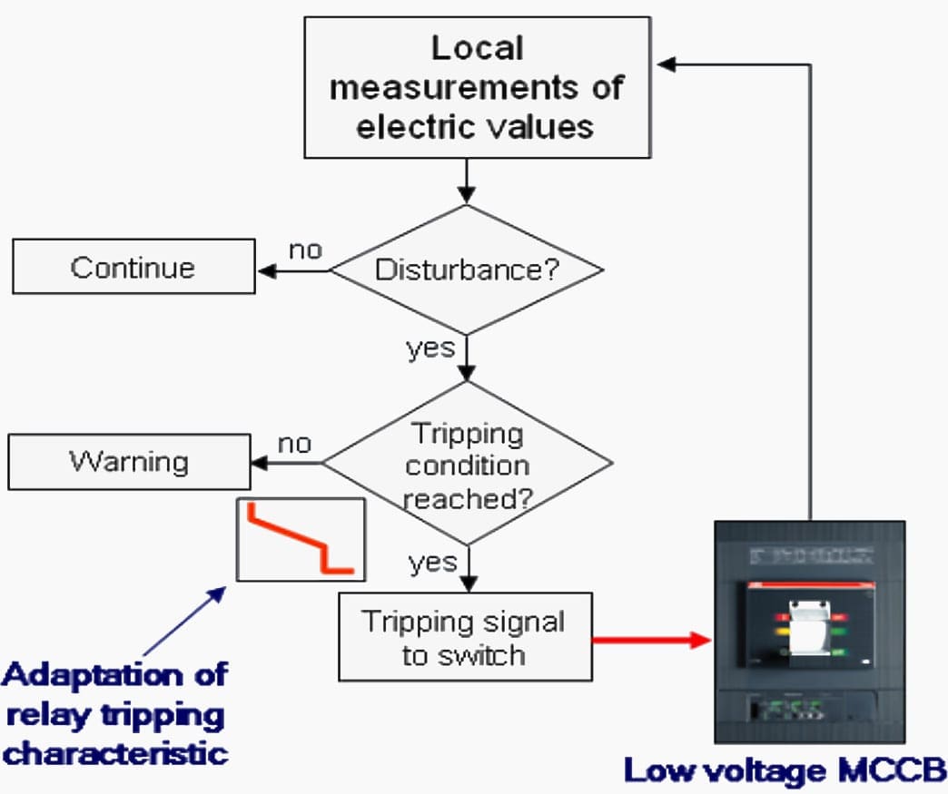
During a fault, the individual digital directional relays sense the fault direction and magnitude, thus can take tripping decision by own (locally) without waiting for MCC operation as shown in Figure 2. A CB is opened in case of tripping condition met, otherwise if there is any abnormal condition arise, then MCC checks and update new tripping conditions to digital directional relays.
In this case, MCC performs operation by measuring current in specific direction and further it is compared with actual relay settings.
The main purpose of adaptive protection scheme is to monitor the microgrid network all the time and run it with updated latest settings. This aim is accomplished through a special module inside MCC which monitors the microgrid network periodically and replace the old settings with latest settings.
This monitoring and updates can be done in two ways, either offline or online. The next subsections focus on the issue related to adaptability.
Off-line adaptive protection
In off-line adaptive protection, microgrid central controller (MCC) construct event table, which means that set of possible meaningful configuration with DG units is formed for off-line fault analysis. The number of element for each record in event table is equal to number of circuit breakers (CB) connected to the microgrid network.
Some CBs have high priority than other CBs, for example the CB connecting MV and LV grids. The event table is binary encoded (for example, CB is close means 1 and CB is open means 0) shown in Figure 3. Then, different faults are applied in all possible location in microgrid network for each configuration of event table and then fault current pass through each relay is recorded in another structure called fault current table.
The microgrid topology and DG unit status (on/off) are also changed during this process. Finally, the directional overcurrent relay settings with time delay are calculated based on these results and stored in another structure called action table. Action table and event table has same dimension.
The flow chart in figure 4(a) shows the steps of off-line adaptive protection scheme.
On-line or real-time adaptive protection
In on-line adaptive protection, the microgrid central controller always monitor the microgrid network including DG units, loads and protective devices. This monitoring is done either periodically or triggered by an event such as protection alarm, tripping of CB etc.
Figure 4 (b) illustrates the sequence of on-line adaptive protection scheme.
IS limiter
IS limiter is considered a fault current limiting device. This device is a combination of current limiting fuse and fast switch connected in parallel. This equipment provides economic and reliable operation against large current
Under no fault condition, current pass through the low impedance fast switch. A control circuit is used to detect the fault and sends tripping command to fast switch so that fault current can flow through fuse which has high breaking capacity. Fuse and switches must be replaced after every operation as IS limiter is a one-time device.
Current limiting effect of IS limiter has shown in Figure 5 above.
| Title: | Best protection practices for microgrid distribution networks – Master of Science Thesis by Syed Golam Mahmud at Tampere University of Technology |
| Format: | |
| Size: | 2.5 MB |
| Pages: | 61 |
| Download: | Here 🔗 (Get Premium Membership) | Video Courses | Download Updates |