Typical Relay and Circuit Breaker Connections
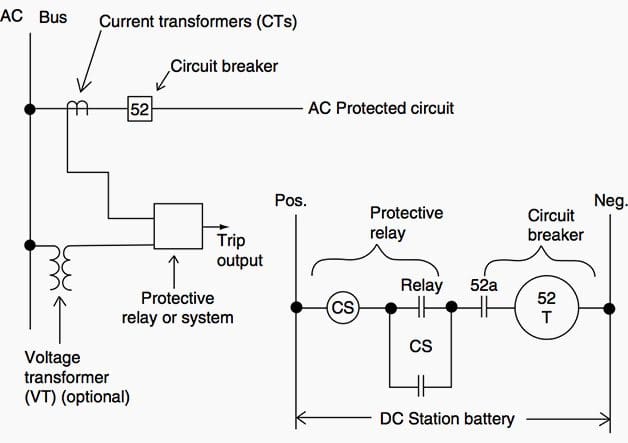
Protective relays using electrical quantities are connected to the power system through current transformer (CT) or voltage transformer (VT). These input devices or instrument transformers provide insulation from the high-power system voltages and reduce the magnitudes to practical secondary levels for the relays.
In circuit schematics and diagrams they are represented as shown in Figure 1.9.
The protective relay system is connected to the AC power system through the CTs commonly associated with the circuit breaker and, if necessary, to the VTs.

These are shown connected to the station AC bus, but often at the higher voltages the voltage devices are connected to the transmission line. The circuit breaker is designated as device 52 following the ANSI/IEEE device number system (IEEE C 37.2).
Thus, when the circuit breaker is closed and in service, its 52a contact is closed. When a system fault operates the protective relay, its output contact closes to energize the circuit breaker trip coil 52T, which functions to open the breaker main contacts and de-energize the connected power circuit.
Basic Objectives Of System Protection
The fundamental objective of system protection is to provide isolation of a problem area in the power system quickly, so that the shock to the rest of the system is minimized and as much as possible is left intact. Within this context, there are five basic facets of protective relay application.
Before discussing these, it should be noted that the use of the term protection does not indicate or imply that the protection equipment can prevent trouble, such as faults and equipment failures, or electric shocks due to inadvertent human contacts. It cannot anticipate trouble.
Thus protection does not mean prevention, but rather, minimizing the duration of the trouble and limiting the damage, outage time, and related problems that may result otherwise.
The five basic facets are:
- Reliability: assurance that the protection will perform correctly.
- Selectivity: maximum continuity of service with minimum system disconnection.
- Speed of operation: minimum fault duration and consequent equipment damage and system instability.
- Simplicity: minimum protective equipment and associated circuitry to achieve the protection objectives.
- Economics: maximum protection at minimal total cost.
Because these are the underlying foundations of all protection, further discussion is in order.
| Title: | Protective Relaying Principles and Applications – J. Lewis Blackburn, Thomas J. Domin |
| Format: | |
| Size: | 6.79 MB |
| Pages: | 638 |
| Purchase: | Here 🔗 (Get Premium Membership) | Video Courses | Download Updates |


thanks alot
Very usful info. Keep up the good work.
EEP is so far one of the best informative site for me with regards to Electrical Engineering.
I wish to thank all the people who continuously spend their precious time contributing and sharing technical documents and information in EEP.
Regards,
Eric Flores, PEE
Really very useful and appreciable work.
Always useful & appereciable
useful reference. thanks
Great Book !
Thanks for the support (-:
A good site for all your engineering needs…kudos
good & excellent reference but shall be more good if actual is suitable with brand :
Siemens Protection Product, SEL Products, etc.
Thanks a lot
Excellent work. I would not miss a single day. Many thanks for your great contribution
Hi,
First of all I have to thank you for the great job you have done. Your site is the best.
But I have a problem the site you have chosen for uploading the files doesn’t accept IP’s from Iran ! I have tried it thousand times, but in vain. Would you please check it ?
Thanks a lot