Search

Premium Membership ♕

Limited Time Offer: Save 15% on PRO Plan with discount code: LRN15 and study specialized LV/MV/HV technical articles and studies.

Home / Download Center / Electrical Engineering Books and Technical Guides / Relay control and protection guides / Restricted earth fault relay application within a 400kV shunt capacitor bank design

Impact on protection stability

This research analyses the performance of the restricted earth fault (REF) relay used on a 400kV capacitor bank scheme used on the Eskom Transmission network. After the commissioning of two capacitor banks using the mentioned scheme design the plant was energized.

Restricted earth fault relay application within a 400kV shunt capacitor bank design (Hydra Substation single line diagram)

As a result of the energization the Shunt Capacitor Bank (SCB) then experienced spurious trips. The cause of the trips was found to be the operation of the restricted earth fault relay.

In this research project, restricted earth fault protection on shunt capacitor banks in the Eskom Transmission environment will be the area of interest.

The proposed research will analyze the current Shunt Capacitor Bank (SCB) protection scheme in service specifically looking at the restricted earth fault circuit design and relay performance.

An equivalent model of the SCB from primary plant perspective based on theory will be derived. Recording and analyzing of Comtrade transient waveforms respectively, when the bank is energized, will be done in order to provide a reference base to work from.

Shows the 400kV 100MVAR Shunt Capacitor Bank at Hydra Substation situated in De Aar
Figure 1 – Shows the 400kV 100MVAR Shunt Capacitor Bank at Hydra Substation situated in De Aar. One can see the individual capacitor elements, surge reactor and earthing capacitors respectively.

Manual calculations of various parameters from the derived model including transient inrush currents and fault currents will be performed to access applicable scheme parameters.

Further calculations will include the voltage setting for the restricted earth fault relay.

As a result of the analysis a recommendation will be made on a viable solution or a revised design will be put forward, based on the results, to improve the scheme’s performance. The protection scheme is used on the two 400kV 100MVAR capacitor banks 11 and 12 at Hydra Substation.

Single line representation of the Shunt Capacitor Bank
Figure 2 – Single line representation of the Shunt Capacitor Bank

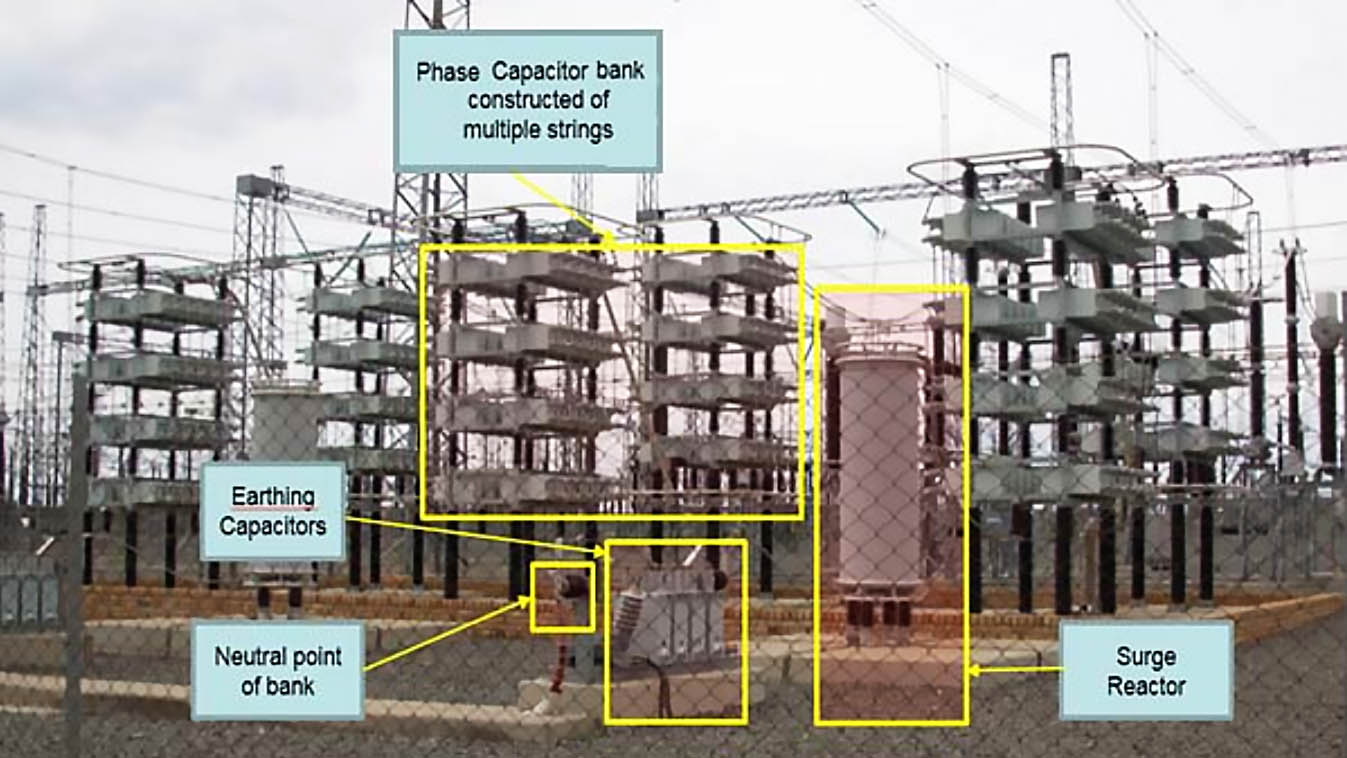
Existing 400KV 100MVAR grounded Wye Bank

Figure 2 above illustrates the single star earthed bank in a single line diagram form. The capacitor bank itself indicates the star connection on a per phase basis.

The outdoor bay comprises of the following switching devices: busbar isolators (off load switching), a circuit breaker for on-load switching and for the isolation of faults, earth switches for safety and maintenance purposes.

The purpose of the reactor is to detune the dominant harmonic current. This includes presenting the shunt compensation as an inductive quantity to the network in order to mitigate resonance between the capacitor bank and the inductive overhead line.

Instead, the series reactor resonates with the capacitor with the affect that their resonant magnitudes cancel each other out.

Title:SAnalysis of restricted earth fault relay application within a shunt capacitor bank design impacting on protection stability – W. Minkley at Nelson Mandela Metropolitan University
Format:PDF
Size:4.00 MB
Pages:115
Download:Here 🔗 (Get Premium Membership) | Video Courses | Download Updates
Restricted earth fault relay application within a 400kV shunt capacitor bank design

Premium Membership

Get access to premium HV/MV/LV technical articles, advanced electrical engineering guides, papers, and much more! It will help you to shape up your technical skills in your everyday life as an electrical engineer.
50% Discount 💥 - Save 50% on all 90+ video courses with Enterprise Membership plan.

More Information

4 Comments


  1. hariom sharma
    Mar 09, 2023

    The Tripping due to REF setting has been explained and the solution is not properly described.it needs to be elaborated as to how these tripping are avoided in practice.


  2. Farham Hosseini
    Feb 18, 2021

    We are looking for all Electronic and Electricity Istandard


  3. Jerry Padayhag
    Feb 16, 2019

    What is the problem if the neutral to ground of Transformer 100kVA has a voltage reading at no load and increases when the transformer has a load. ?


  4. Prabhakar Samal
    Feb 15, 2019

    Good topic plz do send .

    Thanks

Leave a Reply to Jerry Padayhag

Tell us what you're thinking. We care about your opinion! Please keep in mind that comments are moderated and rel="nofollow" is in use. So, please do not use a spammy keyword or a domain as your name, or it will be deleted. Let's have a professional and meaningful conversation instead. Thanks for dropping by!

1  ×    =  six

Learn How to Design Power Systems

Learn to design LV/MV/HV power systems through professional video courses. Lifetime access. Enjoy learning!

Subscribe to Weekly Newsletter

Subscribe to our Weekly Digest newsletter and receive free updates on new technical articles, video courses and guides (PDF).
EEP Academy Courses - A hand crafted cutting-edge electrical engineering knowledge