
Protective Relays Setting Value
The scope of study involves calculating the settings for protective relays to achieve selectivity during faults ocurring in the electrical network for the 13.8 kV and 4.16 kV projects. The protective philosophy is fundamentally grounded on the understanding that faults or abnormal operating conditions can result in overloads, phase-to-phase and three-phase faults, as well as phase-to-ground faults.

The protective relays are responsible for detecting the previously mentioned events, primarily to isolate the faulty segment from operation and disconnect it from the electrical distribution system. The relay settings have been chosen to provide dependable system operation while maximizing the duration and extent of service for the feeders or the system, minimizing the danger of damage.
The settings exceed any transient current, voltage, and frequency, and the intervention times permit the restoration of these electrical parameters to their regular operating values.
2. How Selectiviy Study is Organized
This Protection Coordination Study is organized into attachments, each corresponding to a certain switchgear, containing the data and results utilized and acquired throughout the project’s development.
The subjects are:
Single-Line Protections Diagrams
The single-line protection diagram is depicted simplest way possible, illustrating the electrical network and the installation points of the primary relays which comprise the protective system.
Transformers & Motors Rating
This subject pertains to the scheduling of machine data utilized for relay coordination.
Figure 1 – Transformers rating table

Relay Setting Table
The relay setting table includes the specifications of the relays (manufacturer, type, setting range), the ratios of measurement transformers (current or voltage), and the setting values for both the primary and secondary sides of the measurement transformers.
The pages containing the coordination curves and the corresponding labels are specified in the columns “curve, page, label“.
Selectivity Curves
The curves that are important for relay coordination are combined with selectivity. The relays are designated with a code, when applicable, to facilitate straightforward identification on the setting tables and coordination sheets.
The code appears in the single-line diagram with a circle for phase relays and an ellipse for ground relays.
Figure 2 – Phase fault selectivity for the Switchboard 5-SW-600

Hypothesis For The Selectivity Study
The selectivity study relies on the estimation of short circuit current calculations and has been analyzed for both maximum and minimum short circuit currents. The fault current depicted in the selectivity diagrams represents the maximum short-circuit current of the relevant switchgear, as determined by short-circuit current calculations, including of motor fault contributions. The selectivity curves for each individual user or feeder are based on the maximum short-circuit fault current permitted.
The maximum phase-to-ground fault current in the 13.8 kV and 4.16 kV electrical networks is 400 A, limited by resistors.
Consideration must be given to the following when interpreting the selectivity diagrams. Indeed, for ground fault selectivity diagrams, the current scale has been reduced by a factor of ten. In the lower left corner of the figures, the multiplying coefficient of the current down the axis is clearly indicated, assuming it differs from one.
The machine data schedules include all the data pertaining to the machines, transformers, and motors utilized in the study. Where data are currently undefined, an asterisk denotes the estimated value.
The transformer withstand limit capability, as indicated in selectivity diagrams with a point, has been assessed to be equivalent to the maximum short circuit current with upstream infinite power, for a length of two seconds.
The selectivity drawings demonstrate the short circuit current withstand capacity of the cables, derived using the equation I2t = k2S2. The coefficient k for copper cables (G7) is expected to be k=143.
The motor protection relay consolidates all essential tasks for the effective protection of motors into a single enclosure. The selective drawings display the motor operating curves and the protection curves as follows: 49-51-50-51LR-48-64. The thermal time constant of the M.V. motor has been set to provide a restart when the preload reaches 90%, which is a common scenario during automated transfer.
The excessively prolonged starting protection has been selected as an inverse time type (I2t), with current and duration corresponding to the starting situation.
The fault current depicted in the selectivity diagrams represents the maximum short-circuit current of the corresponding bus, as determined by short-circuit current calculations, including of motor fault contributions. Therefore, the fault contribution via the transformer will be lower than this value.
The high settings for overcurrent protection on the primary side of the transformer are determined by the maximum let-through fault current of the transformer, considering the source power and transformer impedance.
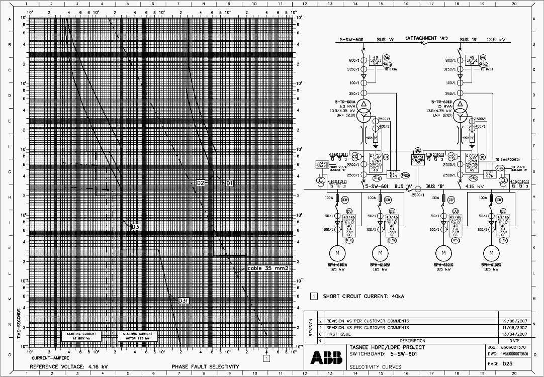
Figure 3 – Phase-fault selectivity for Switchboard 5-SW-601
Results Of The Selectivity Study
The primary criteria employed for the protective settings are the combined amperometric and chronometric selectivity. The primary objective is to guarantee comprehensive and reliable protection for the relevant feeder, followed by selectivity with upstream and downstream measures.
Selectivity is guaranteed for phase and ground faults throughout the whole 13.8 kV and 4.16 kV electrical distribution network.
Medium voltage ground fault selectivity (fault current restricted to 400 A):
- Motor and transformer feeders: ground overcurrent relays are supplied by ring current transformers, allowing for minimal settings. Settings are presumed to be between 10 and 40 A (the primary value).
- The incoming and bus tie ground overcurrent relays are supplied by a residual connection from phase current transformers. To prevent false trips during transient phenomena, primarily inrush or phase faults involving current with a DC component, a specific time characteristic has been chosen with a setting of 6-10% of the current transformer rated current.
ABB REF 542 protection relays provide two separate alternative configurations that can be modified through a communication channel. The plant’s characteristics do not necessitate distinct settings; so, the primary and secondary settings are identical.
The settings of 13.8 kV incoming relays must be validated with upstream relays to ensure selectivity between protections.
| Title: | Relay Coordination Study: Calculation of the protective relays setting value to obtain selectivity |
| Format: | |
| Size: | 4.5 MB |
| Pages: | 125 |
| Download: | Here 🔗 (Get Premium Membership) | Video Courses | Download Updates |
Further Study – Relay protection coordination study on 150 kV HV network
Relay protection coordination study on 150 kV high voltage transmission network

An interesting and comprehensive discussion on cause and effect of faults on powerlines. Congratulations on completion of a useful practical guide.
This portal seems to me very interesting because here a lot of SLD are given with protection system .Due that reason i appreciate this portal .
Thanks & Regards
Engr Md Shah Alam
Thank you very much, Engr Md Shah Alam!