Protection Settings
The documents presented should serve as a model to various utilities in preparing similar documents for setting protection relays installed installed at 220kV, 400kV and 765kV EHV and UHV transmission systems.

The numerical terminals referred as IED (Intelligent electronic device) contain apart from main protection functions several other protection and supervision functions which may or may not be used for a particular application.
Thus, it is important that the recommended setting document should contain all the settings for all functions that are used and indicate clearly the functions not used (to be Blocked / Disabled).
This shall be followed not only for Line protection IEDs but also for other IEDs like Generator, Transformer, Reactor, Bus bar protection and Control functions.
Basic System parameters
Network line diagram of the protected line and adjacent circuits
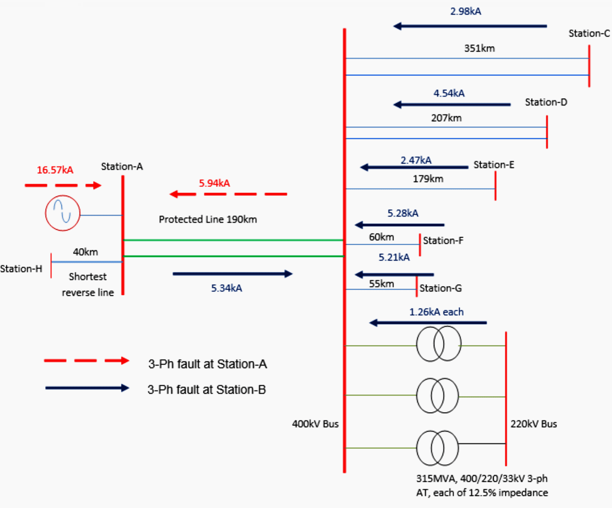
The network line diagram (Figure 1-1) of the system under consideration showing protected line along with adjacent associated elements should be collected.
The network diagram should indicate the voltage level, line length, transformer/generator rated MVA & fault contributions of each element for 3-ph fault at station-A and for 3-ph fault at Station-B.

Single line diagram of the double circuit line
Equivalent representation of the protected line based on network line diagram indicated at Figure 1- 1 is prepared as shown in Figure 1-2 indicating the source fault impedance at station-A and Station- B, positive and zero sequence impedance of the protected line.

Line parameters
- Line: Substation-A to Substation-B
- Frequency: 50Hz
- Line data:
R1 + jX1 = 0.0288 + j0.307 Ω/km
R0 + jX0 = 0.2689 + j1.072 Ω/km
R0M + jX0M = 0.228 + j0.662 Ω/km - Line length: 190km
- CT ratio: 1000/1A
- CVT ratio: 400/0.11kV
Maximum expected load on line both import and export: This shall be obtained from the load flow analysis of the power system under all possible contingency. From the load flow studies, 1500MVA is the maximum expected load under worst contingency on this line at 90% system voltage.
| Title: | Model setting calculations, line protection setting guidelines, protection system audit check list and recommendations for protection management – Sub-committee on relay/protection under task force for power system analysis under conntigencies |
| Format: | |
| Size: | 12.4 MB |
| Pages: | 468 |
| Download: | Right here | Video Courses | Membership | Download Updates |


