
Protection simulation with SEL relays
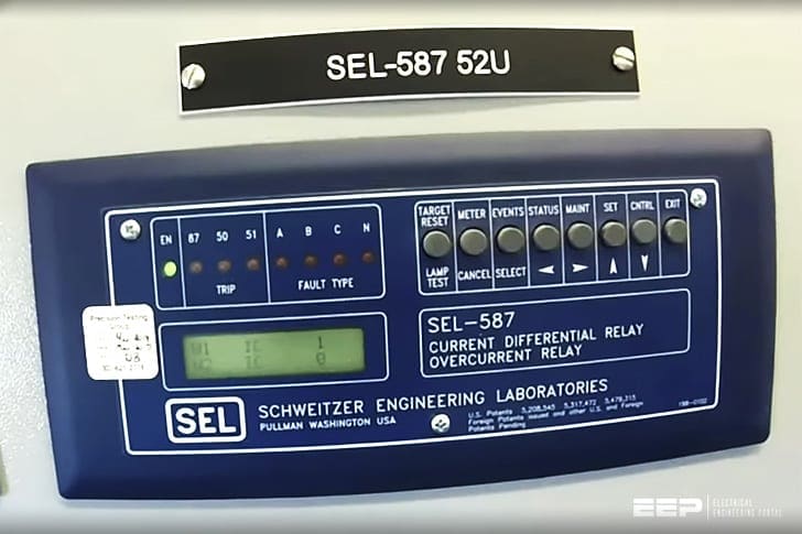
This project simulates protected system that includes a source, circuit breaker, transformer, and motor. Schweitzer Engineering Laboratory’s (SEL) protection relays are used to open breakers during fault conditions on transformers (SEL 587) and motors (SEL 710).
First, analysis was done on each of the individual components to test for functionality. Testing the transformer and motor separately provided the relay and circuit breaker coordination during fault conditions. The motor was protected against phase-to-ground, line-to-line, locked rotor, and temperature faults.
As for the 3-phase transformer, the SEL 587 protected against phase-to-ground, line-to-line, and 3-phase faults.
The motivation behind this project started with the idea of having students simulate a power distribution protection system within a Cal Poly lab. After the analysis was done on the protection system, the student is able to understand how sources, transformers, motors, relays, and breakers work as a system to provide power to an end user.
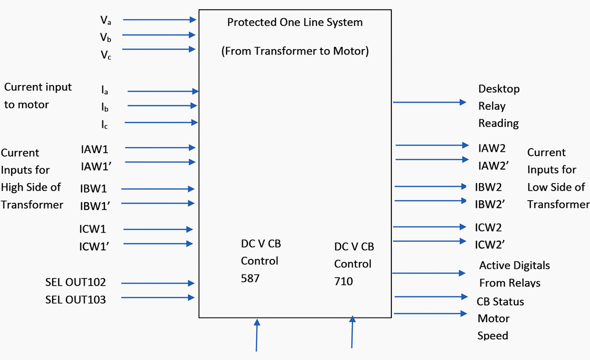
Students take on the responsibility of each component in the motor-transformer system and understand what are the important inputs or outputs.
In Figure 1, the level zero diagram shows the inputs and outputs found within the motor-transformer system.
In conclusion, the motor-transformer system will simulate a protection scheme for different types of loads.
For example, irrigation systems will have multiple motor-transformer combination off the same bus that vary in horsepower. Each of these motor-transformer combinations need to provide adequate voltage and current to supply the load, while protecting against different types of faults.
| Title: | Simulation of protection system that includes a source, transformer and motor – Senior Project by Bijan Vakilifathi at California Polytechnic State University, San Luis Obispo |
| Format: | |
| Size: | 2.80 MB |
| Pages: | 45 |
| Download: | Right here | Video Courses | Membership | Download Updates |

Hi,
We are an importers and distributors of thermal overload protectors of brands like – Thermik , Microtherm etc but now we want to start our own manufacturing of Thermal Overload Protectors which we import from China i.e. 17AM. We are looking for consultants who can help us setting up a manufacturing unit in India.
These are very useful information’s,