
Introduction to transformer protection
Power transformers of medium and large sizes are very critical and vital components for power systems. Due to its significance and cost, its protection needs to be appropriately addressed. Transformer protection should be fast and reliable. To provide early cautioning of electrical failures and prevent disastrous losses, appropriate monitoring of power transformer should be selected.
This results in the damage limit and the reliability improvement of the power supply. The requirements of the protective relays include dependability (no missing operations), security (no false tripping), speed of operation (short fault clearing time) and stability. Therefore, a transformer differential relay is used to meet the protection requirements of the medium and large power transformers.
The differential scheme approach compares the currents at the primary and secondary on the protected zone of the transformer by calculating and monitoring a differential current.
In case the computed value of the differential current is greater than the set value, this indicates an internal fault.
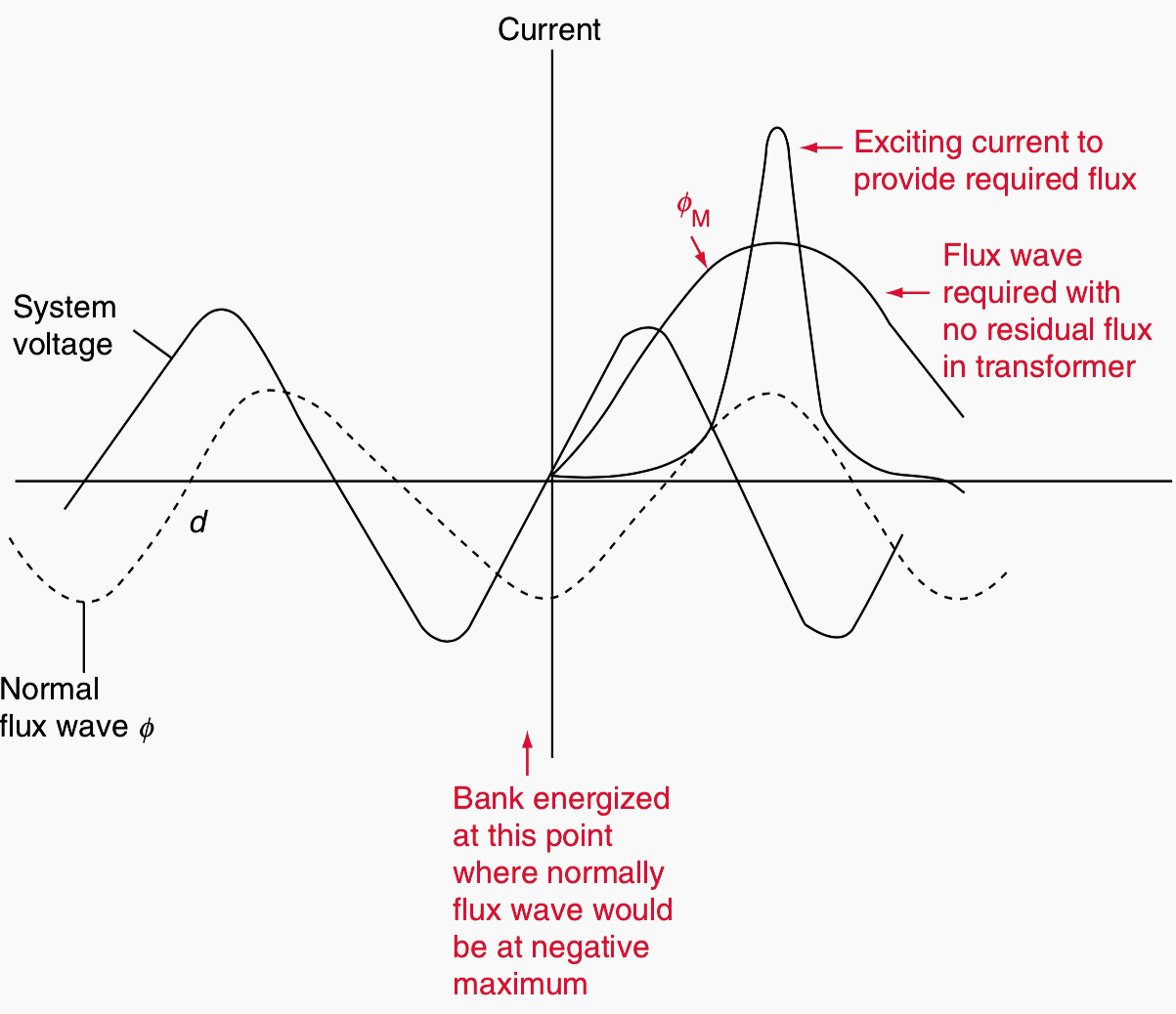
The inrush condition results in the saturation of the transformer core. Magnetizing inrush current that arises in a transformer is identified by comparing the polarity and magnitude of residual flux which does not correspond to polarity and magnitude of an ideal instantaneous value of steady-state flux.
Magnetizing inrush current can be as high as ten times of full load current. The inrush condition phenomenon would typically cause the trip element of the transformer differential to mis-operate, if not adequately blocked or restrained.
Transformer inrush currents usually are rich in harmonics in general and in second harmonic particularly. The second-harmonic ratio is traditionally used for transformer differential protection in order to block or restrain the differential trip elements during transformer magnetizing inrush current conditions.
Presently there are three types of schemes that are being used for the magnetizing inrush current determination:
- First scheme makes use of data obtained from the transformer incoming currents only. The method is based on the principle of second harmonics restraint.
- Second scheme makes use of information that is obtained from the transformer terminal voltage variation. This method is based on the voltage restraint principle.
- Third scheme makes use of information that is obtained from both the transformer’s currents and voltages. This method is based on the flux characteristic principle using the low-voltage acceleration criterion.
This thesis used the first scheme which is the second harmonic restraint method for magnetizing inrush current determination. Extra reliability to the power system is provided by the backup overcurrent protection schemes.
The main protection which is the transformer differential scheme may fail due to:
- The mechanical defect of moving regions of the transformer differential relay,
- Transformer differential relay DC supply failure
- Tripping pulse of the transformer differential relay failure to the breaker
- Current or voltage supply failure to the transformer differential relay from CT or VT circuits
However, this thesis is not considering the above failure conditions of the transformer differential scheme. In this specific situation, another type of protection called backup overcurrent relaying scheme is applied. Hence, backup overcurrent relaying scheme has every configuration setting separate from the main transformer differential protection.

The reason is the backup overcurrent relay must not fail to operate in case of the failure of the main protection scheme. As a backup overcurrent protection scheme, it must be slower in action than the main differential protection one, so that it should only work in case the main differential protection scheme of the transformer fails.
With reference to Figure 2 above, the transformer differential relay has the magnetizing inrush current function, which blocks the differential relay from tripping for inrush conditions. Nevertheless, the overcurrent relay employed as backup protection to the transformer differential protection scheme does not have the inrush current function, and it will trip during inrush conditions.
This thesis used the differential relay SEL-487E as the main protection and backup overcurrent protection SEL-751A.
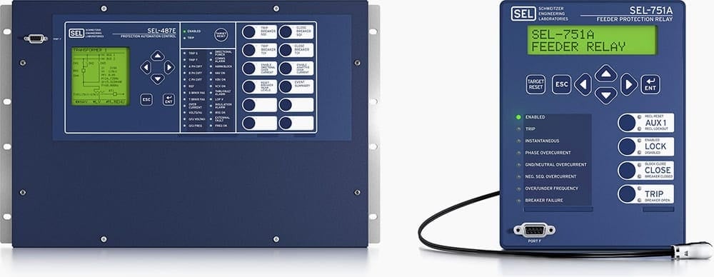
In order to restrain SEL 751A overcurrent relay from tripping during inrush conditions, a blocking scheme based on second harmonic restraint current is employed. The second harmonic restraint scheme uses the harmonic blocking element (87HB) of the SEL-487E to send a blocking signal to the SEL 751A to inhibit it from tripping during inrush current conditions.
The IEEE 14-bus system is simulated in the DIgSILENT and RSCAD software environments to generate a fault and inrush current conditions. The lab-scale test bench setup is implemented to test the phase percentage differential protection schemes using SEL-487E IED and Omicron CMC 356 test injection device.
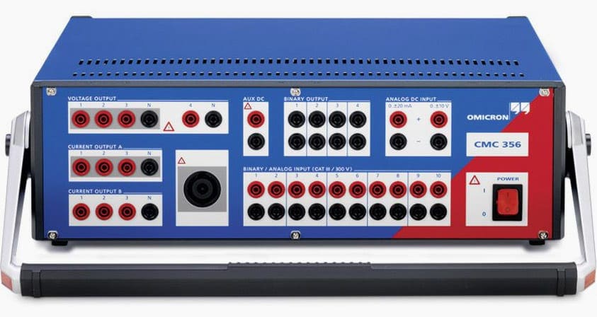
The demonstration of the IEC 61850 standard-based reverse harmonic blocking scheme is implemented in the CSAEMS laboratory using Omicron test injection device CMC 356, SEL-487E and 751A protection IEDs. Finally, implementation and testing of the IEC 61850 standard-based hardware-in-the-loop simulation are performed using RTDS and protection IEDs.
The hardware-in-the-loop simulation is conducted for external and internal faults and inrush current conditions

The research aim is to investigate hardwired and IEC 61850 GOOSE applications to the transformer protection schemes. The test bench setup provides the lab scale illustration of how the physical power transformer is protected by using differential protection (SEL-487E), and backup overcurrent (SEL-751A) relays as shown in Figure 5.
For internal events, the SEL-487E and SEL-751A IEDs current coils are energised and send trip signals to the binary contact of the test injection device as shown in Figure 1.2.
The pickup and trip signal of the circuit breakers are represented using the binary signal connected to the output port (OUT101) of the SEL-487E and (OUT102 and OUT103) of the SEL-751A, which are mapped to the binary inputs 1 and 2 of the test injection device as shown in Figure 5.
| Title: | Advanced protection scheme for power transformers based on IEC 61850 standard – Bwandakassy Elenga Baningobera; Thesis submitted in fulfilment of the requirements for the degree Master of Engineering: Electrical Engineering in the Faculty of Engineering At the Cape Peninsula University of Technology |
| Format: | |
| Size: | 6.7 MB |
| Pages: | 357 |
| Download: | Right here | Video Courses | Membership | Download Updates |


hi,
thanks. Can you help me know the IEC Standard for fire protection on the power transfomer. On behalf of my client i am searching for the right directive of IEC to help him . sorry if i am wrong in asking this to you.
Thanks!
Good article, very educative.
Thank you Ajetomobi, feel free to download the Study (PDF).