Protection arrangements for feeders
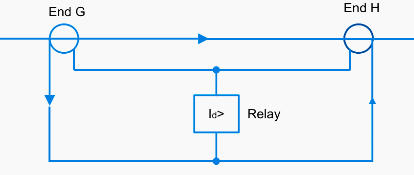
Fundamental differential arrangements have established the foundation of many sophisticated protection arrangements for feeders and other system elements. In certain protection schemes, an auxiliary ‘pilot’ circuit interconnects similar current transformers at each end of the protected zone.

This is presented in Figure 1 below.
Current running through the zone causes secondary current to circulate round the pilot circuit without generating any current in the protection relay. For a short circuit within the protected zone the CT secondary currents will not balance, in comparison with the through-fault condition.
The difference between the currents will flow in the protection relay.

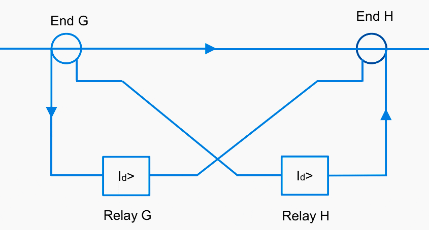
An optional scheme is presented in Figure 2. In this arrangement, the CT secondary windings are opposed for through-fault conditions so that no current runs in the series connected relays.
The first protection arrangement is known as a ‘Circulating Current’ system.

The second protection arrangement is known as a ‘Balanced Voltage’ system. The majority of unit protection systems work through the determination of the relative direction of the fault current.
Fault current direction can only be presented on a comparative basis, and such a comparative measurement is the typical factor of many protection systems, including directional comparison protection and distance tele-protection protection schemes with directional impedance measurement.
One of the most important factors of unit protection is the communication method between the protection relays.
| Title: | Unit Protection of Feeders – Velimir Lackovic, Char. Eng at Continuing Education and Development, Inc. |
| Format: | |
| Size: | 410 KB |
| Pages: | 33 |
| Download: | Here 🔗 (Get Premium Membership) | Video Courses | Download Updates |


It is pleasant to note the technical discussion & information provided by this website.
It is pleasant to note the technical discussion & information provided by this website.