Introduction
The energy sources for electrical installations are AC generators and transformers. All these generators, however perfect, have an internal impedance which has two major effects:
- in normal operating conditions, this impedance causes voltage to drop from no-load condition to bring it to Un when the generator delivers In;
- when a short-circuit occurs this impedance limits the current to a value given in multiples of In
To take the example of transformers, their shortcircuit voltage Ucc (as a %) corresponds to the upper limit of their relative voltage drop under rated current, In.
For example, an Icc of In/5 % = 20 In is obtained for a short-circuit voltage of 5%, i.e. a current of 29 kA for a 1000 kVA/400 V transformer. It is not hard to imagine the damage such a current could cause in an installation (temperature rises and electrodynamic forces are proportional to the current square!). Thus, even if all precautions are taken to make such an occurrence unlikely, protective devices are still needed to break the short-circuit currents.
Definition of currents to break
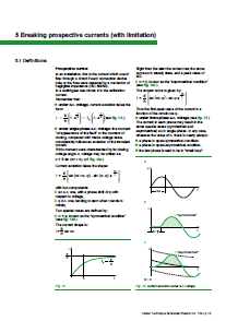
Current breaking is dependent on a number of parameters relating to generators (a.c. generators or transformers), lines and loads:
- an electric circuit is always inductive, and thus the very fluctuations in the current to break, generate, as soon as the circuit is opened, negative current feedback which help maintain the current. The value of this back-electromotive voltage of the L di/dt type may be high whatever the value of current i until this current is cancelled;
- the resistive value of the circuit to break is of assistance in breaking as long as the current is high, but ceases to be of any help when current tends to zero, since the ohmic drop is then negligible;
- the capacities between live conductors, whether distributed (“stray” capacities of generators and cables) or additional (capacitor bank in reactive energy compensation or filter), alter breaking conditions;
- the frequency of the current to break, since in theory it is easier to break a.c. currents with periodic zeros than d.c. currents;
- finally, the voltage delivered by the generator.
Once the current has been cancelled, thebreaking device must dielectrically withstand the mains voltage still present.
AUTHOR: Schneider Electric expert | Robert MOREL
| Title: | LV circuit-breaker |
| Format: | |
| Size: | 0.7MB |
| Pages: | 31 |
| Download: | Right here | Video Courses | Membership | Download Updates |


