
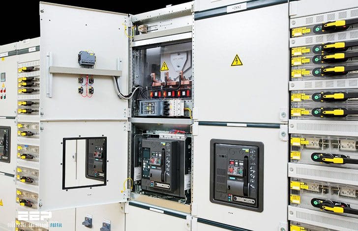
Switchboard construction
Frame
There are multiple elements that make up a switchboard. Included in the list of elements are a frame, buses, overcurrent protective devices, service metering, and outer covers.
The frame of the switchboard houses and supports the other components. The standard Siemens switchboard frame is 90 inches high and 32 or 38 inches wide. An optional height of 70 inches with widths of 32, 38, or 46 inches is also available.
Siemens switchboards have a depth measurement ranging from 20 to 58 inches.

Bus
A bus is a conductor or set of conductors that serves as a common connection for two or more circuits. NEC® article 408.3 states that bus bars shall be located so as to be free from physical damage and shall be held firmly in place.
Rear Connected Switchboards
Siemens Rear Connected (RCS) switchboards feature individually mounted branch and feeder devices. Because of this method of mounting, access to outgoing cable terminations must be from the rear of the switchboard.
Bus bar extensions from the feeder devices are run back to the rear of the unit for easy access. The front and rear of all sections align.
RCS switchboards accommodate systems up to 6000 amperes, 600 volts maximum in any three-phase three-wire or three-phase four-wire configuration. The main bus can be specified for 600 to 6000 ampere rating.

RCS Switchboards use WL insulated case (UL 489) or LV power (UL 1 066) circuit breakers with drawout mountings and continuous current ratings from 400 to 5000 A for main and branch devices.
Integrated Power System (IPS) Switchboards
The modular design of Siemens Integrated Power System (IPS) switchboard allows the customer to integrate electrical distribution equipment, power monitoring, and environmental controls that typically mount in multiple enclosures into one switchboard line-up.
Customers have the freedom to configure an arrangement that best fits their individual needs. Optional factory installed interconnection wiring is available to further reduce installation time.
IPS switchboards are built to UL 891 and NEMA PB-2 standards. IPS sections have a standard height of 90 inches. Optional 70 inch high sections are available. The minimum depth of IPS sections is 1 3.75 inches. Optional depths of 20, 28, and 38 inches are available and these optional depths may be required depending upon the components installed.
- Lighting panelboards (MLO and main device)
- Power monitoring devices
- Distribution transformers
- ACCESS communication
- Lighting contactors
- Lighting control
- Heating ventilation and air condition (HVAC) control
- Building management equipment
- Programmable logic controller (PLC)
- Automatic transfer switch (ATS)
- Motor starters
- Backup generators
IPS switchboards consist of one service section and one or more distribution sections that are cable connected. However, IPS switchboards are also available with through bus and pull sections.
IPS switchboards accommodate systems up to 4000 amps, 600 VAC maximum in 1 -phase, 3-wire; 3-phase, 3-wire; and 3-phase, 4 -wire configurations.
| Title: | Basics of Switchboards – SIEMENS |
| Format: | |
| Size: | 2.8 MB |
| Pages: | 60 |
| Download: | Right here | Video Courses | Membership | Download Updates |


Hello, sir/madam
We, kibogate Tanzania Limited Electrical contractor currently participating in TENDER No: TP/02/2021/ICB/G/004 for supply, Testing and Commission of below list equipments flouted by TANZANIA INTERNATIONAL PETROLEUM RESERVES LTD (TIPPER).
We request your office to give the prices for named Equipment below;
1. 4000A LV Auto-changeover Switchboard (IP 31 free Standing Form2 50kA) Comprising incomers 1No 2500A 4P ACB (66kA@400V LI Protection) for Gen 4, 1No 4000A 4P ACB (66kA@400V LI Protection) for T2, 1No 630A 4P Motorized ACB for Gen 2, 1No 4000A 4P ACB (66kA LI Protection) Bus coupler, 1No 1600A 4P ACB (66kA@400V LI Protection) for Gen 3, 1No 3200A 4P ACB (66kA@400V LI Protection) for T1, 1No 630A 4P Motorized ACB for Gen 1. Each incomer is provided with 1set Phase indication lamps, 1No Digital MF meter, 1No Current Monitoring Relay (Signaling Exceeded incomer load). Outgoings: SECTION 1: 7Nos 1000A 3P MCCBs (50kA@400V Adjustable Protection),1No 1250A 3P MCCB (50kA@400V Adjustable Protection). SECTION 2: 3Nos 1000A 3P MCCBs (50kA@400V Adjustable Protection), 1No 1250A 3P MCCB (50kA@400V Adjustable Protection), 1Nos 2000A 3P ACBs (42kA LI Protection), All outgoings Provided with status Indication Lamps (ON, OFF, TRIP). PLC Control is provided for Electrical interlocking & Transfer from Utility to the Generators based on Load demand and control of Buscoupler. Make of Major items: ABB. Make of PLC and control cards: Siemens.
We also request the followings
1. Manufacturing Authorization letter.
2.CODES, STANDARDS SPECIFICATIONS
Supplied materials and equipment should conform to;
a. International Electro technical Commission (IEC) 60439-1: Low voltage switchgear and control gear assemblies, part 1
b. IEC 60364-1: Low voltage electrical installations, part 1
3.Original of Internationally Published Brochures in English language.
4. Material specifications for all the parts and Cross sectional drawings of all the important parts.
5. List of recommended service tools and the cost.
6. Original maintenance and operational catalogues/manual.
7. Detailed testing and commissioning plan.
8. Preventive maintenance schedule with maintenance instructions
9.List and prices of recommended spare parts of the components of the electrical system for period of 2 years
10.Guarantee and warranty periods of components of the Electrical System at least 2 years.
Hope for your positive respond.
Thanks
Eng. Isaya Sifuel
Project Coordinator
Hi
Are you able to do switchboard design (schematics and SLD with shop drawing basics) as per IEC61439
hi, can u tell me about Energy Automation System in lv. how can i know the element that used between Control Room HMI and LV-Compartments.
thanks for sharing ur information
Testing Procedure and the reference readings for impedance, insulation, RCD and earth fault.
Thanks for sharing information