
Introduction
This Siemens’ guide covers three chapters:
- High voltage substations,
- Medium voltage substations and
- Low voltage substations.
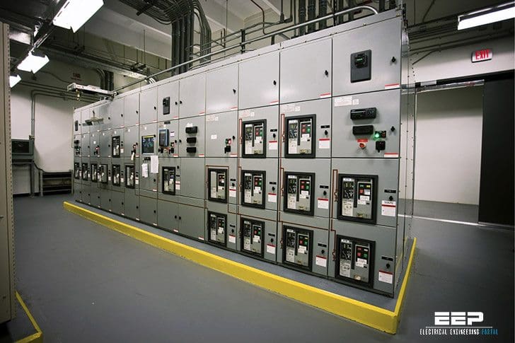
Low voltage main distribution
When selecting a low voltage main distribution system, the prerequisite for its efficient sizing is knowing about its use, availability and future options for extension. The requirements for power distribution are extremely diverse.
Normally, frequent switching operations need not be considered in the planning of power distribution for commercial, institutional and industrial building projects, and extensions are generally not to be expected. For these reasons, a performance-optimized technology with high component density can be used.

In these cases, Siemens mainly uses circuit breaker protected equipment in fixed-mounted design.
The use of circuit-breaker protected technology in withdrawable design is important. Selectivity is also of great importance for reliable power supply. Between these two extremes there is a great design variety that should be optimally matched to customer requirements.
The prevention of personal injury and damage to equipment must however, be the first priority in any case. When selecting appropriate switchgear, it must be ensured that it is a design verified switchgear assembly (in compliance with AC 61439-2, VDE 0660-600-2), with extended testing of behavior in the event of an internal arc fault (IEC 61641, VDE 0660-500, Addendum 2).
Low voltage main distribution systems should be chosen among those featuring a total supply power up to 3 MVA.

Up to this rating, the equipment and distribution systems are relatively inexpensive due to the maximum short-circuit currents to be encountered.
For rated currents up to 3200A, power distribution via busbars is usually sufficient if the arrangement of the incoming, outgoing feeder panels and coupler panels has been selected in a performance-related way. Ambient air temperatures, load on individual feeders and the maximum power loss per panel have a decisive impact on the devices to be integrated and the number of panels required, as well as their component density (number of devices per panel).
Arc resistance
Arcing faults can be caused by incorrect dimensioning and reductions in insulation due to contamination etc., but they can also be a result of handling errors.
The effects, resulting from high pressure and extremely high temperatures, can have fatal consequences for the operator, the system and even the building. SIVACON offers effidence of personal safety through testing under arcing fault conditions with a special test in accor-dance with IEC 61641 (DIN VDE 0660-500 Addendum 21.
Passive protections increase personal and system safety many times over. These include: hinge and locking systems with arc resistance, the safe operation of withdrawable units or circuit breakers behind a closed door and patented swing check valves behind venitlation openings on the front, arcing fault barriers or arcing fault detection system combined with the rapid disconnection of arcing faults.
| Title: | Switchgears and Substations Guide – SIEMENS (3rd chapter of Power Engineering Guide, Edition 7.1) |
| Format: | |
| Size: | 6.8 MB |
| Pages: | 78 |
| Download: | Right here | Video Courses | Membership | Download Updates |


more information on bus riser, bus coupler and bus tie
its good but i need constuction and working..
Hi dear manager
I like to understand about microgride and operation in uncertainty aspects. Reliability of microgride in esthetics operation and planning.
If you can help me .Please send me useful book .articles and book.or useful links.
Thanks a lot
said homeili
this is very simple question and not the standard of engineer