
Introduction to the calculator
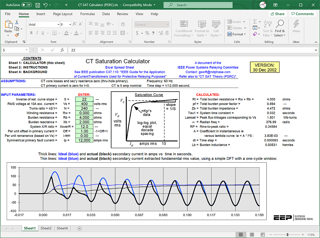
The spreadsheet ‘CT Saturation Calculator’ is intended to provide quick indication not only of whether or not a CT will saturate in a particular application, but also an accurate indication of the actual waves-hape of the secondary current so that the degree of saturation as a function of time is apparent. Furthermore, the data is available to the user to use as input to a digital relay model, if such is available.
The user can convert the data into a COMTRADE file, for example. There are many technical papers on the subject of modeling the behavior of iron-cored current transformers used for protective relaying purposes. One of the difficulties in using an elaborate model (in any field of engineering) is in getting the parameters in a particular case in order to implement that model easily, efficiently and accurately.
For example, the excitation current in the region below the knee-point is a complex combination of magnetizing, hysteresis and eddy-current components, the parameters of which are usually not known in a particular case.
If errors under low current, low burden conditions are of interest, a more elaborate model must be used.
Testing of the Model
The proof of the pudding is in the eating. Because this model is new and quite different from those in the literature, testing against real high-current laboratory results was important. To this end, two laboratory examples published in reference (*) were compared against results from this program. The agreement was very close.
In addition, the program has had widespread circulation, and to date there are two utility-user reports of agreement with previous results and no reports of disagreement.
(*) Tziouvaras, D.A., et al, Mathematical Models for Current, Voltage, and Coupling Capacitor Voltage Transformers
Instructions
The first step is to determine the saturation voltage (Vs) for the CT in question. This is defined as the rms excitation voltage corresponding to ten-per-cent error current. For example, for a nominal five-amp CT which is expected to handle 100 amps with a ten per cent error, the error current at the saturation voltage Vs, is ten amps.
Incidentally, the actual measurements by the manufacturer may not have been made with a “true rms” meter. It has been determined that the error due to use of a “rectified average” type meter, for example, is not significant.

Second step is to determine the slope (1/S) of the upper part of the saturation curve, being careful that the curve is plotted on log-log scales with the decade spacing equal on both axes. “S” is defined as the reciprocal of this slope. You should get a slope such that S is in the neighborhood of 15 < S < 25. Note that the result is not very sensitive to the value of S.
Third and the last step: Enter other parameters such as the CT winding resistance, the burden, the degree of dc-offset in the primary current waveform (up to 1 per unit), the primary system X/R ratio, the remanence (*), and the primary symmetrical rms current.
Once any change to an INPUT parameter is made, a new plot appears automatically. The scale adjustment is automatic and the plot is believed to be self-explanatory.
So when we specify 10 amps error current at 100 amps secondary current, the error is actually less than 1% typically, but includes a phase error of, say 5 degrees, leading.
(*) Note that the per unit remanence is defined relative to Vs. If the knee-point voltage (45 degree slope point) is 80% of Vs, then the maximum remanence value is 0.8. Note that the polarities for this simulation are such that a positive remanence is the “worst-case” condition for premature saturation.
| Software: | Current transformer (CT) saturation calculator |
| Version: | – |
| Developer: | IEEE |
| Size: | 2.30 MB (.xls) |
| Price: | Free |
| Theory: | Here 🔗 (Get Premium Membership) | Video Courses | Download Updates |
| Download: | Here 🔗 (Get Premium Membership) | Video Courses | Download Updates |

I also developed a spreadsheet to do the job.
Magnetizing hysteresis was also considered.
The original spreadsheet is freely available from the developer at https://www.pes-psrc.org/kb/report/044.xls
Gostaria de ter acesso a planilha.
Thank you
thanks
is it possible to share excel sheet, thanks
I NEED SPREAD SHEET TO CALCULATE LOAD BANK TO COMPENSATE CT AND PT BURDEN
excelent
Thankyou
I would like to apply the CT calculation for 1A or 5A nominal.
I have seen this spreadsheet 5 years ago. It belongs to GE. But here I have not seen any reference to the original work. Please add the reference.
i want to level up my career
Very useful information. Thanks.