
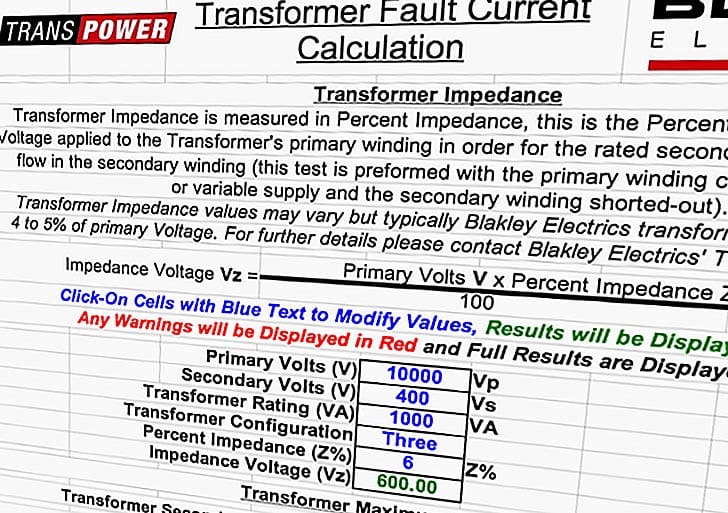
Transformer Impedance
Transformer Impedance is measured in Percent Impedance, this is the percentage of rated primary voltage applied to the Transformer’s primary winding in order for the rated secondary Full Load Current to flow in the secondary winding (this test is preformed with the primary winding connected to a Variac or variable supply and the secondary winding shorted-out).
Transformer Impedance values may vary but typically Blakley Electrics transformers will be between 4 to 5% of primary Voltage.
For further details please contact Blakley Electrics‘ Technical department.
Transformer Maximum Fault Current Allowing for Loog Impedance
To calculate the Maximum Fault Current that can be achieved in a circuit fed by a transformer we refer to the below formula.

This formula calculates the loop impedance at the end ofa circuit fed from the secondary winding of a transformer. When calculating Fault Loop Impedance Select the Correct Transformer Type Above. Three Phase Transformers Divide the Values for Vs secondary Voltage by √3 and the VA by 3.
For Centre Tapped to Earth (C TE) transformers halve the values for Vs and VA . For RLV / 110V C TE Disconnection Times & Zs figures refer to BS 7671:2008, 411.8 Table 41.6.
| Software: | Transformer Fault Current Calculation – Blakley Electrics |
| Version: | 2.0 |
| Developer: | BLAKLEY Electrics |
| Size: | 110kB |
| Price: | Free |
| Downloads: | Right here | Video Courses | Membership | Download Updates |


very cool
Very Good platform for brushing the Fundamentals. Excellent approach.
Please keep it up
I like this site a lot its really good
I download the calculator but don’t’ work, I can’t change the values.
Please let me know what can I do.
Thanks for your support
You have to click enable editing
I like this site, its ery helpful… Thank you and more power to all of you!
There might be some problem about the 3^(1/2)
10/10
Very helpful – thank you
i like this site nice
Keep up the good work
thank you
very cool
this site
helps lot.
I like this site a lot its really good.