
Transformer Losses
Transformers have two major components that drive losses: the core and the coils. The typical core is an assembly of laminated steel, and core losses are mostly related to magnetizing (energizing) the core.
These losses, also known as no-load losses, are present all the time the transformer is powered on – regardless of whether there is any load or not.
Core losses are roughly constant from no-load to full-load when feeding linear loads. They represent a continuous cost, 24 hours/day, for the 25-year or more life of the transformer.
Formulas in spreadsheet
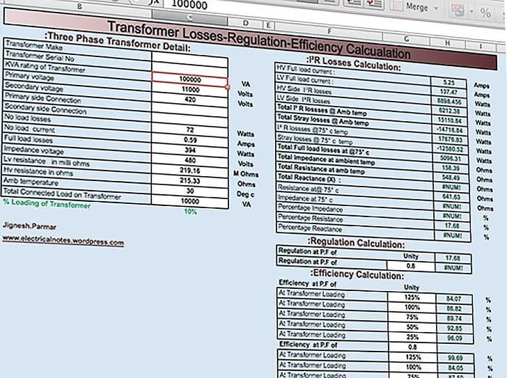
- HV Full load current = VA / (1.732 · Volt)
- LV Full load current = VA / (1.732 · Volt)
- HV Side I2R losses = I²R · 1.5
- LV Side I²R losses = I²R · 0.5 · 3
- Total I² R lossses at Amb. temp = Hv losses + Lv losses
- Total Stray losses at Amb. temp = Measured losses – I²R losses
- I²R lossses at 75° C temp = ((225 + 75) · losses) / (225 + Amb. temp) .
- Stray losses at 75° C temp=((225 + Amb. temp)(Stray losses at Amb. temp)) / 300
- Total Full load losses at 75° C = I²R losses at 75° C + Stray losses at 75° C
- Total Impedance at amb. temp = (Imp. voltage · 1.732) / Full load current
- Total Resistance at amb. temp = I²R losses / I²
- Total Reactance (X) = SQRT (Impedance² – Resistance²)
- Resistance at 75° C = (300 · resistance at amb ) / (225 + Amb. temp)
- Impedance at 75° C = SQRT (R² at 75° C + X²)
- Percentage Impedance = (Z at 75° C · I · 100)/V1
- Percentage Resistance = ( R 75° C · I · 100)/V1
- Percentage Reactance = (X · I · 100) / V
- Regulation at Unity P.F. = (%R cosø + %Xsinø)
- Regulation at 0.8 P.F. = (%R cosø + %Xsinø) + 1/200(%R sinø – %Xcosø)2
Efficiency at Unity P.F
- At 125 % of Transformer Loading = (kVA · 1.25 · 100)/((kVA · 1.25)+(I²R losses · 1.25²)+(No Load Losses))
Efficiency at 0.8 P.F
- At 125 % of Transformer Loading = (kVA · 1.25 · P.F. · 100)/((kVA · P.F. · 1.25)+(I²R losses · 1.25²)+(No Load Losses))
Contribution to transformer losses
Load level varies widely, with some installations running very heavily loaded and others more lightly loaded.
This difference substantially impacts actual losses incurred. Unfortunately, there is a small body of field data available, driven by the factors such as a lack of awareness of the cost of the losses, and the cost of gathering detailed data from a reasonable number of individual transformers.
Since there are a wide variety of transformers on the market serving different purposes, and available from different manufacturers, actual losses incurred in the field will vary substantially from installation to installation.
| Software: | Spreadsheet for Transformer Losses Calculation |
| Version: | 10.06.2013 |
| Developer: | Jignesh Parmar |
| Size: | 36 Kb |
| Price: | Free |
| Download: | Right here | Video Courses | Membership | Download Updates |


Temperature correction factor formula
(PKt)=((235+75)/(235+Am.tem)×load loss for copper as know before and used practically
Temperature correction factor formula
(PKt)=((225+Am.tem)×(stray loss at Am.tem))/300 .for aluminium academically
Can we use both interchangeable for copper & Aluminium practically?
Temperature correction (Kt)=((235+75 )/(235+Am.temperature))×load loss for copper.
Temperature correction (Kt)=((225+75)/(225+Am.temperature))×load loss for Aluminium
As proposed on the spreadsheet formula at 75 degree for load loss and Stray loss they used as follows
Loss at 75 degree Celsius
((225+75)/(225+Am.tem)×loss
Stray losses also
((225+Am.tem)(stray losses at Am.tem))/300
What is their difference of them? 225 , 235 & 300 time we use?
Could you provide me a worksheet to calculate losses of a 500kV transmission lines?
Need to calculate transformer looses.
Need software to download
Yes I need
Which software i can use
Thanks for everything
Which software i can use
We are using 415 V ac, 50 Hz, 600Amp, dimmerstate (variable voltage transformer).
Need help in calculating losses. CORE loss and COIL (Copper) Loss.
We are using 415 V AC, 50Hz, 600 Amp, Variac.
We want to calculate I2R Losses (Cu-Losses)
In Copper loss, why it is multiplied by 1.5 and 0.5 for HV & LV side?
How do I get the Impedance when having,
315KVA transformer
5,5KV
16,55A
Dear sir
Thanks in advance
could you tell me and solve the problem of how to calculate the x/r of Transformer?
I hope you will learn to me !!!
HOW TO CALCULATE FULL LOAD AND NO LOAD POWER LOSS IN DISTRIBUTION TRANSFORMER
Hello,
How to calculate the no load loss, copper loss and stray loss for 2500KVA Transformer(33KV/0.433KV). Do share the formulas for all the 3 types of losses in transformer.
it is very useful for me
Dear Jignesh,
I don’t find Lv resistance nor Hv resistance (cells C16 and C17 in your Excel file) on my transformer user manual. I though at first that it was primary side resistance and secondary side resistance. But in that case, I don’t understand why you multiply by 0.5 in the I²R losses formula (cells H7 and H8).
I thought it might be total resistance seen from primary and secondary, thus I computed I²R losses / I1² and the same with I2², but figures are different.
Please, can you explain me how to find these values (Lv and Hv resistance) ?
With kind regards
Denis
Dear sir,
How to calculate 2500KVA (11kv/415V) Transformer no load loss and copper loss at 50% rated load.
Transformer details:
Make- Crompton
YOM- 2007
KVA- 2500
Impedance volts- 7.10%
HV Amp- 131
LV Amp- 3333
Volts HV- 11000
Volts LV- 433
Type of cooling- ONAN
Please reply me as soon as possible.
Regards,
Pankaj Patel
9879735195
Gujarat, India
Dear Mr. Pankaj patel,
This is very simple to measure no load losses.
First of all Switch off the transformer output breaker, which is installed on LT side called ACB. Then take Clamp meter and measure the Amps from transformer input (HT side) and put the amps in power formula, (P=HT Volt*HT Amps*pf*1.732/1000) P=11000*0.5*0.8*1.732/1000
Regards
Please share me formula for our very urgently required
Dear Sir,
Thank you for posting this calculator. I used it to check my own which was almost correct.
Sir, please note that we have old 400 kva tranformer,year of manufactured 2007 and MAKE: CROMPTON GREAVES. OIL COOLED TRANFORMER Hence kindly suggest us for replacement of the TRANSFORMER , since it is very old.we are assuming that lot of energy getting wasted due to the above conditions.
You can go with Esennar Transformers.. where you can save upto 50 thousands rupees per year..
Assuming the losses and impedance of the transformer is negligible, calculate the HV and LV currents if the transformer was loaded at 120%
What formula use ?
Sir, coul you explain temperature gradient calculation of HV and LV winding , if temperature rise 40/50
Please tell how to calculate no load losses of transformer.
Tell me how to get transformer copper loss
I have no load losses n total power loss
Total Power loss = No load loss + Copper loss + Stray loss
If assume Stray loss negligible then
Copper loss = Total power loss – No load loss
Dear sir,
Dry type and oil type transformer losses how to calculate.
specs of hi pot tester from 10 to 35kv?
How can I calculate no load losses and load losses of power trafo when I have total losses of trafo available only?
Great work, keep it up ^_^
On this formula: Total Stray losses at Amb. temp = Measured losses – I²R losses, if I measured V= 384, I= 20 and W= 1015, for a 24MVA, 231200V (on tap 1), how do I relate the measured power into the equivalent input power which I can use in the formula?
The spreadsheet for transformer losses calculations is a good work
how do find out the value of resistance in hv and lv side
please review cell H33, i think efficiency should not be highest at 125%
Dear all,
How can I get the value 1.5 in ” HV Side I2R losses = I²R · 1.5″ and 0.5*3 in
” LV Side I²R losses = I²R · 0.5 · 3″ .
Thank you in advanced.
Dear all,
What are the values 1.5 in HV and 0.5*0.3 and LV ?
HV Side I2R losses = I²R · 1.5
LV Side I²R losses = I²R · 0.5 · 3
Thank you in advanced.
IEC60076-1, Clause 10.2 specified that: “The resistance of each winding, the terminals between which it is measured”.
It means in short-circuit test to get resistance values, they will measure the resistance between two transformer terminals (A-B, B-C & C-A).
HV – Delta Connection: Rwinding = Rmeasured x 1.5
[Because they measured terminal – terminal while 1Rwinding // (Rwinding + Rwinding)]
LV – Star connection: Rwinding = Rmeasured x 0.5
[Because they measured terminal – terminal while Rwinding + Rwinding]
HV – Delta connection: Current through winding Iw = I/sqrt(3)
LV – Star connection: Current through winding Iw = I
So now we calculate the copper loss (resistance loss): 3 windings so that we have to multiple with 3
HV – Delta connection: 3 x Iw x Iw x Rw = 3 x I/sqrt(3) x I/sqrt(3) x R x 1.5 = I x I x R x 1.5
LV – Star connection: 3x Iw x Iw x Rw = 3x I x I x R x 0.5 = I x I x 0.5 x 3
Dear sir,
For finding i^2R losses on hv side =I^2R.1.5
What does 1.5 means
Dear Venjateswar,
Did you find any answer for this question ?
Best regards,
Hello!
what is V1 and V for the percentage impedance and reactance?
Thanks!
The V1 is the voltage that, applied to the HV side of the Tx whose voltage rating is V, shall circulate the rated current on the LV side of the Tx with it’s terminal short circuited. This voltage is expressed as a %age.
Z%=(V1/V)*100.
Is the measured loss a physically measured value? Is there a way of estimating this number based on the transformer size?
Edvard / Jignesh
well done gents this is practical and useful I like it!.
Here is a suggestion for you ready reckoner spread sheets for estimating:
overhead power lines e.g. 415V AC distance covered number of bends and calculate the number of posts, cross arms, insulators, conductor sizes, tension, weight of the conductors….
same for 22kV or 33kv or underground with approximate schedules of rates so I can enter local steel costs ideal pole spacing typical sag heights….
can you provide spreadsheet for transformer losses calculation of 1000kva
Can’t you use this spreadsheet? Just edit field rated power in kVA.
How can we convert this losses to thermal losses?
They are thermal origin. Find out more here:
https://electrical-engineering-portal.com/transformer-heat-copper-and-iron-losses
EEP provides much more information about any given electrical article which is guide line for technical people.
Thank you Ahmad!